
|
|
|
| page created : August 30th, 2008 | last update : January 10th, 2010 (mistake in code) | author : Claude Baumann | ||||||||||||||||||||||||
| Abstract: This page presents a fast method for digital phase detection of two signals in the time domain. These signals are digitalized at high sampling speed using a 1-bit ADC. A certain number of samples are stored in the system memory. Then the digital values pass an eXclusive OR-gate (XOR) in order to produce a bit pattern indicating which samples do not correspond between both signals. The logical result of the operation is integrated over time. The XORing is repeated with one signal being bitwise shifted against the other. The minimum of the integrate and its argument is determined. The latter is equivalent to the initial time-lag of both signals. The method can easily be implemented into small microcontroller systems, requiring only a small portion of memory. It is very fast compared to other digital methods like the cross-correlation or the sum of absolute difference method. The efficacy of the algorithm is illustrated through the implementation into the LEGO™ RCX module that is used in combination with a stereo audio amplifier forming a binaural sensor that is capable of discriminating the time-lag between the signals that arrive on two microphones. The phase detection just takes 100ms in the case of 2x1000 samples (sampling process included) | ||||||||||||||||||||||||||
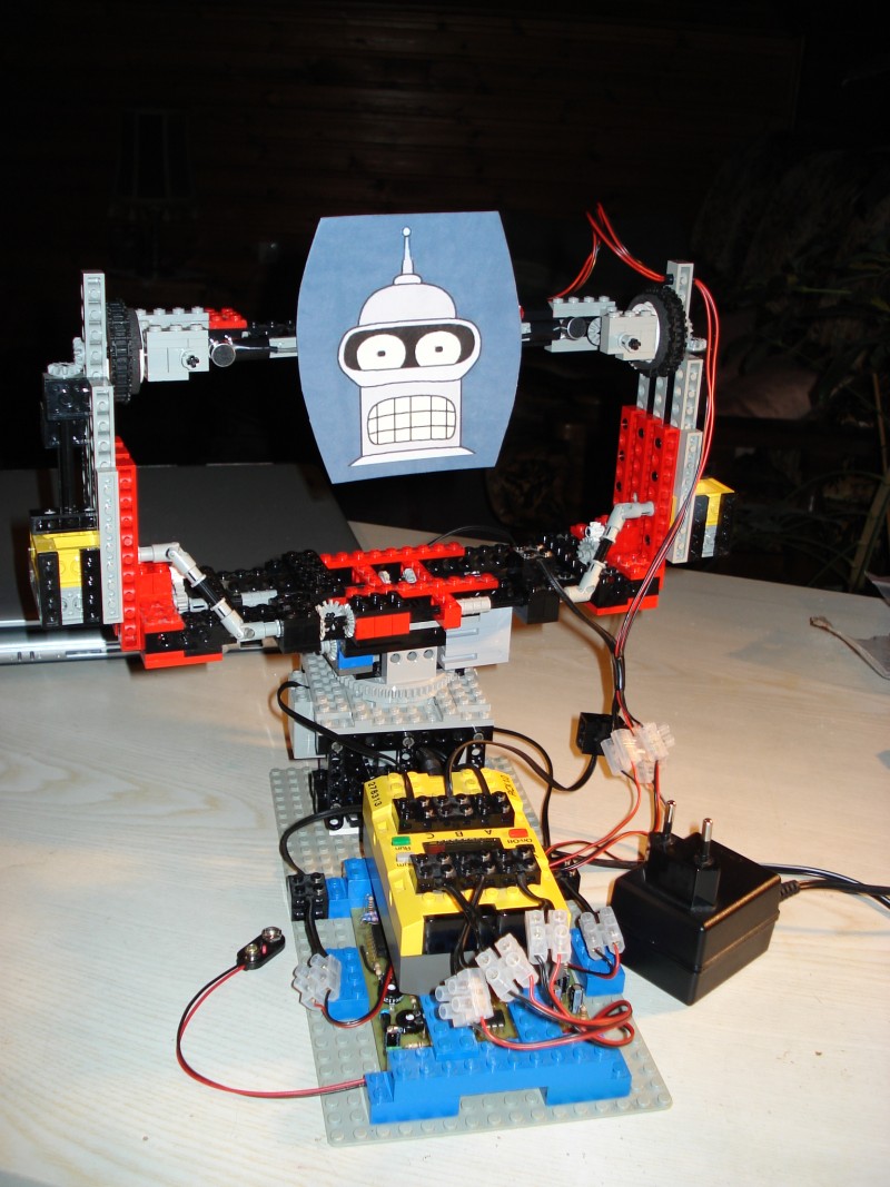
| Robot: Nic_3, a spatial sound localizing robot. | ||||||||||||||||||||||||||
| Video: A small radio is emitting sound waves in the horizontal plane. The robot listens and turns the head (rather abruptly) towards the sound direction. The room reverberation causes some errors in cues. So, the robot must retry, but rapidly fixes the radio with its laser beam. The motion could be improved by ramping the motor power. There also are a few issues with the fact that sometimes Nic_3 listens to its own motor noise, because the NXT does not yet send a message back to the RCX telling it that the movement has been completed. Another problem has appeared: we are no longer certain that the audio sampling rate still is 36kHz. We will need some more testing to determine this rate exactly. We suppose that through the additional code in the sampling process, the rate dropped to about 33-34kHz. (From the code the rate cannot be deduced easily, since the RCX H8 instruction execution depends on the access speed to RAM. Thus, another experiment is needed.) The repercussion is that the computation of the azimuth is biaised. ==> Stand-by for the further developments !!! | ||||||||||||||||||||||||||
Previous work:
|
||||||||||||||||||||||||||
Bill of material:
|
||||||||||||||||||||||||||
|
Figure 1: Two coherent audio signals -in
the sense of [BLAUERT1997,
p. 201]- are sampled with the RCX using the ULTIMATE
ROBOLAB® high
speed sampling feature through the Nic_3 two-channel audio sensor. (The RCX
has a 10-bit ADC that converts two signals at a sampling rate of 36kHz.) The
signals are a out of phase. The green and the blue overlapping bars
represent the most significant bit (msb) of each ADC channel over time.
These bits are XORed, which means that the result only is a logical
"1", if both arguments are different from each other. The
"1"s are counted and listed into a histogram.
|
||||||||||||||||||||||||||
|
Figure 2: The signals are shifted
against each other. In this example, the bit-bars almost completely overlap. The XOR-operation
distillates those bits that do not correspond. They are counted and noted on
the histogram list.
|
||||||||||||||||||||||||||
|
Figure 3: Only the relevant time-lags are
considered. (In the example, the signals, being recorded from the binaural
sensor, may not lag for more than 24 samples on each side, the microphone
spacing being 20cm.) The abscissa of the minimum on
the histogram indicates the initial time-lag of the signals. The non-linear
shape of the histogram changes in function of the signal form. This makes a
function of the integrated XORed data to the time-lag unreliable. (Note
that analog phase detectors that linearize the time-lag proportionally to
the XORed "1"s integrate present the issue of being unprecise for
complex signals.) However, the argument of the minimum does not change its
location, if the signals change in form or amplitude.
|
||||||||||||||||||||||||||
|
Figure 4: If the signals are noisy, the number of logical "1"s changes
a lot from one phase detection process to the next. The determined minimum of the histogram also varies, but if the
data passes a FIR filter (depth 25 in this example), the result is a rather stable value.
|
||||||||||||||||||||||||||
Function summary:
|
||||||||||||||||||||||||||
Software:
|
||||||||||||||||||||||||||
H8/3292 Assembler code of the sampling and
phase detection process:
              //
              //Fast phase detector subroutine for binaural sensor
              //Author CB, August 2008, version 1.0
              //
              //expect differences from pseudo-code at
              //www.convict.lu/htm/rob/phase_detection.lu
              //especially all the loops decrement
              //therefore the bit_index must start with 0
              //because arrays are being filled from the right
              //also variable "g" is replaced with pointers
              //
              //For easy debugging, all variables are in
              //global memory or registers
              //
              //Assembler partly generated by ULTIMATE ROBOLAB
              //
              //sub tau
label begin_of_sub_tau
              //****************begin of sampling part*****************
              //disable all interrupts
              //during sampling
              orc #0x80
              //set sensor1 to 9V
              mov.b @0xFFBB,r6L
              or #0x4,r6L
              mov.b r6L,@0xFFBB
              //define array
              //L_8 @0xCEB8
              //define array
              //R_8 @0xCF38
              //Configure ADC
              mov.b #0x19,r6L
              mov.b r6L,@0xFFE8
              //Initialize registers for sampling process
              //r0 : pointer to L_8-array ; initialized with last byte
              //r1 : pointer to R_8-array ...
              //r2 : pointer to R_8 root address
              //r3L and r3H : last sampled values; initialized with 0x7F
              //r4L : bit_index
              //r5/r6 : standard use for moves
              mov.w #0xCF37,r0
              mov.w #0xCFB7,r1
              mov.w #0x7F7F,r3
              mov.b #0x0,r4L
              mov.w #0xCF38,r2
              //For k=(M-1)+R_pointer downto 0+R_pointer
label beginloop_k_loop
              cmp.w r2,r1
              bcs endloop_k_loop
              //start ADC
              mov.b @0xFFE8,r6L
              or #0x20,r6L
              mov.b r6L,@0xFFE8
              //IF x_L > 127 then set current bit
              //else clear the bit
              cmp.b #0x7F,r3H
              bhi true_1080
              jmp false_1080
label true_1080
              bset r4L,@r0
              jmp endif_1080
label false_1080
              bclr r4L,@r0
Label endif_1080
              //IF x_R > 127 then set current bit
              //else clear the bit
              cmp.b #0x7F,r3L
              bhi true_1079
              jmp false_1079
label true_1079
              bset r4L,@r1
              jmp endif_1079
label false_1079
              bclr r4L,@r1
Label endif_1079
              //IF bit index = 7 then reset bit index
              //and decrement the pointers, else
              //increment the bit index
              cmp.b #0x7,r4L
              beq true_1078
              jmp false_1078
label true_1078
              mov.b #0x0,r4L
              subs #0x1,r0
              subs #0x1,r1
              jmp endif_1078
label false_1078
              inc r4L
Label endif_1078
              //Wait for ADC completion
label wait_for_A_D_completion
              mov.b @0xFFE8,r6L
              btst #7,r6L
              beq wait_for_A_D_completion
              //clear flags
              and #0x5F,r6L
              mov.b r6L,@0xFFE8
              //get x_L from ADC channel (upper 8 bits)
              mov.w @0xFFE0,r6
              mov.b r6H,r3H
              //get x_R from ADC channel (upper 8 bits)
              mov.w @0xFFE2,r6
              mov.b r6H,r3L
              //NEXT iteration
              jmp beginloop_k_loop
label endloop_k_loop
              //re-enable interrupts
              andc #0x7F
              //******************end of sampling part*******************
              //******************begin of phase detection part**********
              //if this saction is made critical, the computing time is
              //reduced by half.
              //now registers have different purposes
              //r0 : i loop index
              //r1 : k2 loop index
              //r2 : =0 used for comparison
              //r3L<0> : carry_flag
              //r4 : unused
              //r5/r6 : normal use for moves
              //r6 also used as index to the noo look-up table
              // MIN = 0xFFFF
              mov.w #0xFFFF,r6
              mov.w r6,@0xD020
              // LAG = 0
              mov.w #0x0,r6
              mov.w r6,@0xD024
              // J = 48
              mov.w #0x30,r6
              mov.w r6,@0xD026
label beginloop_1082
              //IF J > 0
              mov.w #0x0,r5
              mov.w @0xD026,r6
              cmp.w r5,r6
              bhi fordo_1082
              jmp endloop_1082
label fordo_1082
              subs #0x1,r6
              mov.w r6,@0xD026
              // SUM = 0
              mov.w #0x0,r6
              mov.w r6,@0xD028
              //i-loop with phase detection
              mov.w #0x7A,r0
              mov.w #0x0,r2
label beginloop_i_loop
              cmp.w r2,r0
              bhi fordo_i_loop
              bra endloop_i_loop
label fordo_i_loop
              subs #0x1,r0
              //get the bytes from L and R
              mov.b @(0xCEB8,r0),r5L
              mov.b @(0xCF3B,r0),r6L
              //compute the bits, where the bytes are different
              //and add NOO-function  result (look-up table @0xCD86)
              //with displacement in r6 to SUM
              xor r5L,r6L
              mov.b #0x0,r6H
              mov.b @(#0xCDB6,r6),r5L
              mov.b #0x0,r5H
              mov.w @0xD028,r6
              add.w r5,r6
              mov.w r6,@0xD028
              bra beginloop_i_loop
label endloop_i_loop
              //IF SUM < MIN
              mov.w @0xD020,r5
              mov.w @0xD028,r6
              cmp.w r5,r6
              bcs true_1083
              jmp false_1083
label true_1083
              // LAG = J
              mov.w @0xD026,r6
              mov.w r6,@0xD024
              // MIN = SUM
              mov.w @0xD028,r6
              mov.w r6,@0xD020
              jmp endif_1083
label false_1083
Label endif_1083
              mov.b #0x0,r3L
              //k2-loop
              mov.w #0x80,r1
              mov.w #0x0,r2
label beginloop_k2_loop
              cmp.w r2,r1
              bhi fordo_k2_loop
              bra endloop_k2_loop
label fordo_k2_loop
              subs #0x1,r1
              //get carry flag from previous iteration
              bld #0x0,r3L
              //get the iterated byte out of L_8
              mov.b @(0xCEB8,r1),r6L
              //rotate the byte with extend carry left
              rotxl r6L
              //store carry flag for next iteration
              bst #0x0,r3L
              //store rotated byte
              mov.b r6L,@(0xCEB8,r1)
              bra beginloop_k2_loop
label endloop_k2_loop
              jmp beginloop_1082
label endloop_1082
              // TAU = 24
              mov.w #0x18,r6
              mov.w r6,@0xD032
              //TAU =TAU - LAG
              mov.w @0xD024,r6
              jsr sys_type_cast_U16_to_I16
              mov.w r6,r5
              mov.w @0xD032,r6
              sub.w r5,r6
              mov.w r6,@0xD032
              //******************end of phase detection part************
              //end_of_sub_tau
              rts 0
|
||||||||||||||||||||||||||
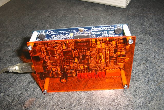
|
DSP module:
|
||||||||||||||||||||||||||
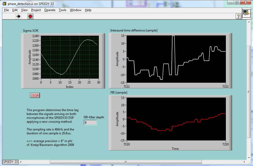
Improvement (added August 2009):
|
||||||||||||||||||||||||||
Notes:
|
||||||||||||||||||||||||||
Literature:
|
||||||||||||||||||||||||||