A sound-sensor for the Cricket that measures the difference of phase
Last modified: 8/10/2001: micro-Farad is not nano-Farad, see yellow marked line
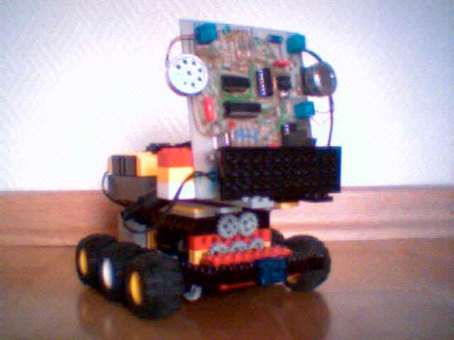
This will be an open growing web-page for our most recent project: an improvement to the cricket. The new sensor to design should be able to
The robot should search and advance towards a pulsing sound-source.
SCHEMATICS (click to see the detail)
The layout and PC-board have been prepared with EAGLE 4.01, a product from CADSOFT. You may get a limited freeware-version of this software. Very useful ! A good auto-router ! This board-layout was conceived for a one-sided circuit. So there remain some vias, a lot of wires not to be forgotten. The spaghetti-circuit is not too beautiful, isn't it, but, regarded the fact that we made a hand-drawn circuit, not so bad either ! (Click to see the circuit without top-layer)
1. POWER-SUPPLY
Obviously, this time we'll need a more powerful supply than the 30mA from an RCX active sensor input. Therefore we use one RCX-output powered to 7 by RCX-software. We'll need:
For best reference control, we add an op-amp stage as voltage follower.
2. EARS
You'll recognize most of the sound-walker's peak detector. The amplification may be changed through R10 and R19. But, as you can see, the last stage has been replaced by the LM 339 comparator to act as a trigger. No signal will give a HIGH (=5V) to the RA0 or RA1 input of the PIC 16F84. A detected peak will set the input(s) to LOW (=0V). The trigger-points are set by the variable resistors R11 and R20.
The time-constant of the peak-detector is
470mF
470nF * 100kW = 47ms, which may
be sufficient.
Our tests however showed a significant signal-jiggering, because of the extreme sensitive LM339. So we think, we'll enlarge the time constant. The next experiences will be made with
C6, C7 = 1 mF
R6, R15 = 220kW
Thus, a time-constant of 220 ms !
3. LEFT / RIGHT DECISION
As you can see, we introduced a PIC into the circuit. Actually this is our first contact with the 16F84 from Microchip . To handle with such a micro-controller, one has to own a programmer, a hardware interface to the PC, where the chip is programmed. We found a design of such a programmer in the French journal Electronique pratique issue decembre 2000 / january 2000 p.40ff, which allows the programming of a large set of PICs (12C508 up to 16F877...) and EEPROMs (12C, 24Cxx or 24LCxx). [ Actually there is a little mistake on page 42. The circuit layer has erronously exchanged IC2 and IC3. Don't do that! ] The programmer works together with the software IC-Prog 1.01, a Dutch freeware program. The .hex file was prepared with Microchip MPLAB, which you can get freely from the Microchip site.
Here the general structure of the PIC program. Of course it has to do some serious action called OK_SIGNAL before the wait_850_ms. In the first program version, either the R or the L bit of the RLSTATUS-variable is set. The signal-LED is activated. In the second version, a new variable has been introduced called SIGNALSTATUS. Only the low-byte is needed. Bit 3 holds the SIGNAL-flag, bit 2 is the RL (right-left) bit. The bits 0 and 1 transport the time-difference between left and right impact (1=Left 0=Right). In the second version, the prescale of the TMR0-timer has been set to 1/64, which provides a 35ms overflow-time.
|
|
Here the .asm file: Don't forget to
disable the watch-dog timer and to set the oscillator to XT.
      LIST  P=16F84
;
PORTA    EQU    5
PORTB    EQU    6
TRISA    EQU    85H
TRISB    EQU    86H
STATUS   EQU    3
INTCON   EQU    0BH
OPTREG   EQU    81H
TMR0     EQU    1
CY EQU 0 ZF EQU 2 RP0 EQU 5 TOIF EQU 2 RIGHT EQU 0 LEFT EQU 2 ; #DEFINE BANK0 BCF STATUS,RP0 ;SELECT BANK 0 #DEFINE BANK1 BSF STATUS,RP0 ;SELECT BANK 1 CBLOCK 0CH ;VARIABLE BLOCK
IDX
TIME
RLSTATUS
FIRST
ENDC
;******************************************************** BANK1 CLRF TRISB^80H ;PORTB ALL OUTPUTS MOVLW B'00000100' ;TIMER0 PRESCALE 1:32 MOVWF OPTREG^80H MOVLW B'00000011' ;CONFIGURE ONLY PORT A0 AND A1 AS INPUTS MOVWF TRISA^80H ; BANK0 MOVLW B'00000011'
ANDWF PORTA,F ;CLEAR PORTA, BUT DON'T AFFECT A0 NOR A1
CLRF RLSTATUS ;RESET FLAGS
NOSIGNAL CLRF   PORTB       ;CLEAR PORTB
         MOVF   PORTA,W     ;W=PORTA
         MOVWF  FIRST       ;FIRST=PORTA
         BTFSS  FIRST,0     ;SKIP IF RA0 IS HIGH = NO IMPULSE ON LEFT MIC
         GOTO   ALPHA       ;IMPULSE FROM LEFT MIC, SO DO ALPHA
         BTFSS  FIRST,1     ;SKIP IF RA1 IS HIGH = NO IMPULSE ON RIGHT MIC
         GOTO   BETA        ;IMPULSE FROM RIGHT, SO DO BETA
         GOTO NOSIGNAL
ALPHA    BCF    RLSTATUS,RIGHT ;LEFT LEFT LEFT LEFT LEFT LEFT
         BSF    RLSTATUS,LEFT  ;LEFT-FLAG SET
         CLRF   TMR0
         BCF    INTCON,TOIF ;CLEAR TMR0 OVERFLOW
WHILE1   BTFSS  PORTA,1     ;SKIP IF RA1 IS HIGH = NO SIGNAL; WAIT UNTIL SIGNAL RIGHT
         GOTO   OKSIGNAL
         BTFSS  INTCON,TOIF ;SKIP IF TIME OVERFLOW
         GOTO   WHILE1
         GOTO   NOSIGNAL    ;TIME OVERFLOW, START AGAIN
BETA     BCF    RLSTATUS,LEFT ;  RIGHT RIGHT RIGHT RIGHT RIGHT
         BSF    RLSTATUS,RIGHT ;RIGHT-FLAG SET
         CLRF   TMR0
         BCF    INTCON,TOIF
WHILE2   BTFSS  PORTA,0     ;SKIP IF RA0 IS HIGH = NO SIGNAL; WAIT UNTIL SIGNAL LEFT
         GOTO   OKSIGNAL
         BTFSS  INTCON,TOIF ;SKIP IF TIME OVERFLOW
         GOTO   WHILE2
         GOTO   NOSIGNAL    ;TIME OVERFLOW, START AGAIN
OKSIGNAL BSF PORTA,2 ;TEST-LED SET AT OK SIGNAL
         MOVF   RLSTATUS,W
         MOVWF  PORTB       ;SET OUTPUTS
;WAIT ROUTINE
         BANK1
         MOVLW  B'00000111'
         MOVWF  OPTREG^80H  ;TMR0 PRESCALE TO 1/256
         BANK0
         CLRF   TMR0        ;RESET TIMER
         BCF    INTCON,TOIF ;RESET TIMER OVERFLOW FLAG
         MOVLW  6           ;W=6
         MOVWF  IDX         ;IDX=6: 6*2.17E-6*256*256=850 msec wait time
LOOP     BTFSS  INTCON,TOIF ;SKIP IF TIMER OVERFLOW
         GOTO   LOOP
         DECF   IDX,F       ;IDX=IDX-1
         BCF    INTCON,TOIF ;reset timer overflow flag
         BTFSS  STATUS,ZF   ;SKIP IF IDX=0
         GOTO   LOOP
         BANK1
         MOVLW  B'00000100' ;TIMER0 PRESCALE 1:32
	 MOVWF  OPTREG^80H
         BANK0
         BCF    PORTA,2     ;CLEAR TEST LED
         GOTO   NOSIGNAL
         END
|
VERSION 2.1 (The time fixing is OK using only 2 bits) LIST P=16F84 ; PORTA EQU 5 PORTB EQU 6 TRISA EQU 85H TRISB EQU 86H STATUS EQU 3 INTCON EQU 0BH OPTREG EQU 81H TMR0 EQU 1 CY EQU 0 ZF EQU 2 RP0 EQU 5 TOIF EQU 2 SIGNAL EQU 3 ;SIGNAL BIT OF SIGNALSTATUS-REGISTER RL EQU 2 ;R/L BIT OF SIGNALSTATUS 1=LEFT 0=RIGHT ; #DEFINE BANK0 BCF STATUS,RP0 ;SELECT BANK 0 #DEFINE BANK1 BSF STATUS,RP0 ;SELECT BANK 1 CBLOCK 0CH ;VARIABLE BLOCK
IDX
TIME
SIGNALSTATUS
FIRST
ENDC
;******************************************************** BANK1 CLRF TRISB^80H ;PORTB ALL OUTPUTS MOVLW B'00000101' ;TIMER0 PRESCALE 1:64 MOVWF OPTREG^80H MOVLW B'00000011' ;CONFIGURE ONLY PORT A0 AND A1 AS INPUTS MOVWF TRISA^80H ; BANK0 MOVLW B'00000011'
ANDWF PORTA,F ;CLEAR PORTA, BUT DON'T AFFECT A0 NOR A1
NOSIGNAL CLRF SIGNALSTATUS;RESET FLAGS CLRF PORTB ;CLEAR PORTB
MOVF PORTA,W ;W=PORTA
MOVWF FIRST ;FIRST=PORTA
         BTFSS  FIRST,0     ;SKIP IF RA0 IS HIGH = NO IMPULSE ON LEFT MIC
         GOTO   ALPHA       ;IMPULSE FROM LEFT MIC, SO DO ALPHA
         BTFSS  FIRST,1     ;SKIP IF RA1 IS HIGH = NO IMPULSE ON RIGHT MIC
         GOTO   BETA        ;IMPULSE FROM RIGHT, SO DO BETA
         GOTO NOSIGNAL
ALPHA    BSF    SIGNALSTATUS,RL ;LEFT LEFT LEFT LEFT LEFT LEFT
         CLRF   TMR0
         BCF    INTCON,TOIF ;CLEAR TMR0 OVERFLOW
WHILE1   BTFSS  PORTA,1     ;SKIP IF RA1 IS HIGH = NO SIGNAL; WAIT UNTIL SIGNAL RIGHT
         GOTO   OKSIGNAL
         BTFSS  INTCON,TOIF ;SKIP IF TIME OVERFLOW
         GOTO   WHILE1
         GOTO   NOSIGNAL    ;TIME OVERFLOW, START AGAIN
BETA     BCF    SIGNALSTATUS,RL ;  RIGHT RIGHT RIGHT RIGHT RIGHT
         CLRF   TMR0
         BCF    INTCON,TOIF
WHILE2   BTFSS  PORTA,0     ;SKIP IF RA0 IS HIGH = NO SIGNAL; WAIT UNTIL SIGNAL LEFT
         GOTO   OKSIGNAL
         BTFSS  INTCON,TOIF ;SKIP IF TIME OVERFLOW
         GOTO   WHILE2
         GOTO   NOSIGNAL    ;TIME OVERFLOW, START AGAIN
OKSIGNAL MOVF   TMR0,W      ;W:=TMR0 CHECK TIME
         BSF    PORTA,2     ;TEST-LED SET AT OK SIGNAL
         BSF    SIGNALSTATUS,SIGNAL ;SET THE SIGNAL BIT
         MOVWF  TIME        ;TIME=W=TMR0
         BTFSS  SIGNALSTATUS,RL  ;skip if LEFT
         COMF   TIME        ;This not function makes sure the RCX-values RIGHT are increasing
         MOVLW  B'00000011' ;TIME MASK
         ANDWF  TIME,F      ;NOW: TIME = '000000XX'
         MOVF   SIGNALSTATUS,W ;W:=SIGNALSTATUS
         IORWF  TIME,W      ;W:=SIGNALSTATUS OR TIME
MOVWF PORTB ;SET OUTPUTS ;WAIT ROUTINE
BANK1
MOVLW B'00000111'
MOVWF OPTREG^80H ;TMR0 PRESCALE TO 1/256
BANK0
CLRF TMR0 ;RESET TIMER
BCF INTCON,TOIF ;RESET TIMER OVERFLOW FLAG
MOVLW 6 ;W=6
MOVWF IDX ;IDX=6: 6*2.17E-6*256*256=850 MSEC WAIT TIME
LOOP BTFSS INTCON,TOIF ;SKIP IF TIMER OVERFLOW
GOTO LOOP
DECF IDX,F ;IDX=IDX-1
BCF INTCON,TOIF ;RESET TIMER OVERFLOW FLAG
BTFSS STATUS,ZF ;SKIP IF IDX=0
GOTO LOOP
BANK1
MOVLW B'00000101' ;TIMER0 PRESCALE 1:64
MOVWF OPTREG^80H
BANK0
BCF PORTA,2 ;CLEAR TEST LED
GOTO NOSIGNAL
END
|
4. TIMING
A 1,8432Mhz-oscillator has been chosen as compromise for three different timing actions to be fulfilled by the internal TMR0-timer of the PIC 16F84:
soundvelocity: c = 343 m/s
If k=14.5cm ==> dt(max) = 0.42 msec. The information we get through dt and the sign of a is not sufficient to fix the triangle exactly. So we try a linear approximation:
a = +/-q.dt, where q= 90. c / k , [q] = [°/sec]
example: k=14.5cm ==> q =2.13E5
if dt = 42ms, a = 9°
The D / A converter of 4 bit seems to be sufficient to communicate the information to the RCX. In the second version of the PIC-program, one bit will is reserved for LR-flag, one for the SIGNAL. Two bits transport the time information. Thus we'll have a resolution of 90 / 4 = 22.5°. If the sensor is well calibrated, a timeout of 140ms will set the first time-bit; 280ms will set the second time-bit; and 420ms will set both bits.
With the 1.8432MHz quartz 1 cycle of the TMR0 (1:1) has a duration of
4 / 1.8432E-6 = 2.1701E-6 sec [4 oscillator-cycles for one timer-action]
at a prescale periode of 1:64 this will give: 1.3889E-4 sec = 140ms. So this prescale is optimal.
5. D / A CONVERTER
As the RCX is only able to read analog values at its input ports, the PIC outputs have to be transformed by a D / A Converter. We do this through galvanic separation with opto-couplers. The parallel resistor-net is activated by the photo-transistors. If the RCX input port is set to no_type and raw_mode, the resistor-net gives the following raw-values according to Mike Gasperi's formula:
RAW = 1023 * R / (10000 + R)
| 8,2k | 15k | 33k | 56k | ||
| B3 | B2 | B1 | B0 | R | RAW |
| 0 | 0 | 0 | 0 | - | 1023 |
| 0 | 0 | 0 | 1 | 56k | 868 |
| 0 | 0 | 1 | 0 | 33k | 785 |
| 0 | 0 | 1 | 1 | 20,8k | 690 |
| 0 | 1 | 0 | 0 | 15k | 614 |
| 0 | 1 | 0 | 1 | 11,8k | 554 |
| 0 | 1 | 1 | 0 | 10,3k | 519 |
| 0 | 1 | 1 | 1 | 8,7k | 476 |
| 1 | 0 | 0 | 0 | 8,2k | 461 |
| 1 | 0 | 0 | 1 | 7,2k | 427 |
| 1 | 0 | 1 | 0 | 6,6k | 406 |
| 1 | 0 | 1 | 1 | 5,9k | 379 |
| 1 | 1 | 0 | 0 | 5,3k | 354 |
| 1 | 1 | 0 | 1 | 4,8k | 334 |
| 1 | 1 | 1 | 0 | 4,6k | 321 |
| 1 | 1 | 1 | 1 | 4,2k | 304 |
The PIC program above (Version 1.0) activates PortB, pin0, if the sound wave touches first the right microphone = RCX-value: 868. If the signal arrives first at the left side, PortB, pin2 will be high, so we will get the value: 614. These values can differ due to part tolerance or probably battery-level of the RCX.
Version 2.0 will render the following values:
Left 67.5 - 90°: 1 1 1 1 --> 304 (RCX raw-value)
Left 45 - 67.5°: 1 1 1 0 --> 321
Left 22.5 - 45°: 1 1 0 1 --> 334
Left 0 - 22.5°: 1 1 0 0 --> 354
Right 0 - 22.5°: 1 0 1 1 --> 379
Right 22.5 - 45°: 1 0 1 0 --> 406
Right 45 - 67.5°: 1 0 0 1 --> 427
Right 67.5 - 90°: 1 0 0 0 --> 461
The RCX-program (Version 1.0)
{This is the first RCX-program for
the phase_sound sensor. There is
a clear right-left distinction}
{.....variables.....}
#define
(EAR,1){....tasks....}
#define
(LISTEN,1)#define(check_and_decide,2)
{....constants.....}
#define
(none,0)#define(Right,1)
#define(Left,2)
beginoftask(main)
setpower(motor_a+motor_b+motor_c,con,7)
on(motor_b)
{turn on phase_sound sensor}setsensortype
(sensor_1,no_type)wait(con,20)
starttask(Listen)
starttask(check_and_decide)
endoftask()
beginoftask(LISTEN)
loop(con,forever)
if(senval,sensor_1,GT,con,900)
{no signal}setvar
(EAR,con,None)else()
if(senval,sensor_1,GT,con,700)
{signal>right-threshold}setvar
(EAR,con,Right)else()
setvar(EAR,con,Left)
{signal left}endif
()endif()
endloop()
endoftask()
beginoftask(check_and_decide)
loop(con,forever)
off(motor_A+motor_C)
while(var,ear,ne,con,none)
{wait until silence}endwhile
()while(var,ear,eq,con,none)
{wait until signal}endwhile
()if(var,ear,eq,con,right)
{sound is right}setfwd
(motor_c) {turn right}setrwd
(motor_a)on(motor_a+motor_c)
wait(con,50)
setrwd(motor_C)
{forward 1 sec}wait
(con,100)off(motor_A+motor_c)
else()
{sound is left}
setfwd
(motor_a) {turn left}setrwd
(motor_c)on(motor_a+motor_c)
wait(con,50)
setrwd(motor_a)
{forward 1 sec}wait
(con,100)off(motor_A+motor_c)
endif()
endloop()
endoftask()
The RCX-program (Version
2.0){phase sound walker
this program should demonstrate
the power of the phase sensor}
{....variables...}
#define
(direction,0)#define(actual_value,1)
#define(action,2)
{...constants...}
#define
(L90,0)#define(L60,1)
#define(L30,2)
#define(Ct,3)
#define(R30,4)
#define(R60,5)
#define(R90,6)
{....subroutines....}
#define
(Left,0)#define(forward,1)
#define(Right,2)
#define(stop,3)
beginoftask(main)
setsensortype(sensor_3,no_type)
{passive sensor}setpower
(motor_a+motor_b+motor_c,con,7)on(motor_a)
loop(con,forever)
gosub(stop)
setvar(action,var,direction)
subvar(direction,con,3)
if(var,direction,LT,con,0)
absvar(action,var,direction)
loop(var,action)
gosub(Left)
endloop()
gosub(forward)
endif()
if(var,direction,eq,con,0)
gosub(forward)
endif()
if(var,direction,GT,con,0)
loop(var,action)
gosub(Right)
endloop()
gosub(forward)
endif()
endloop()
endoftask()
beginofsub(left)
setfwd(motor_b)
setrwd(motor_c)
on(motor_b+motor_c)
wait(con,10)
off(motor_B+motor_c)
endofsub()
beginofsub(forward)
setrwd(motor_b+motor_c)
on(motor_b+motor_c)
wait(con,50)
off(motor_B+motor_c)
endofsub()
beginofsub(right)
setrwd(motor_b)
setfwd(motor_c)
on(motor_b+motor_c)
wait(con,10)
off(motor_B+motor_c)
endofsub()
beginofsub(stop)
{stop and check direction}wait
(con,100) {time to silence down}setvar
(actual_value,senval,sensor_3)while(var,actual_value,GT,con,500)
{no signal, so wait}setvar
(actual_value,senval,sensor_3)endwhile()
if(var,actual_value,LT,con,330)
setvar(direction,con,L90)
endif()
if(var,actual_value,LT,con,348)
if(var,actual_value,GT,con,330)
setvar(direction,con,L60)
endif()
endif()
if(var,actual_value,LT,con,360)
if(var,actual_value,GT,con,348)
setvar(direction,con,L30)
endif()
endif()
if(var,actual_value,LT,con,400)
if(var,actual_value,GT,con,360)
setvar(direction,con,Ct)
endif()
endif()
if(var,actual_value,LT,con,430)
if(var,actual_value,GT,con,400)
setvar(direction,con,R30)
endif()
endif()
if(var,actual_value,LT,con,450)
if(var,actual_value,GT,con,430)
setvar(direction,con,R60)
endif()
endif()
if(var,actual_value,LT,con,480)
if(var,actual_value,GT,con,450)
setvar(direction,con,R90)
endif()
endif()
endofsub()