RCXs
communicate with each other over an asynchronous 1-wire connection.
Rocker-bogie
comparable design for the rover with the restrictions that it won't be
possible to have individual motors for the 6 wheels.
The
rover randomly moves over the simulated Mars terrain and measures the
data on the listed sensors, which then is transmitted to the PC in RF
range. Finally the PC control program uploads the data graphs to a website
via ftp-protocol, where they can be seen from anywhere.
No,
or at least only limited RCX hacks this time !
Why
aren't we doing this with the NXT? The answer is simple: we are under time
pressure. (The robot will be shown at an exhibition soon.) We aren't specialists
enough of the new studless LEGO design. There doesn't remain enough time for
long-duration tests. However the RCX-based robots worked so well during the
previous Mars-projects, both on the hardware and the software side. An NXT
edition will be reserved for the 5th edition.
We still are in the "find how others did
it" phase. Brian Davis points out in his latest
post that anyway the efficiency of the solar panel devices is described
through the weight to power ratio. We conclude that we will have to set up a
balance sheet of all energy losses and gains.
The boost circuit seems to be the most
interesting one, although there also will be losses. The positive points are
that we still get power from the panels, if the voltage dops below the battery
voltage.
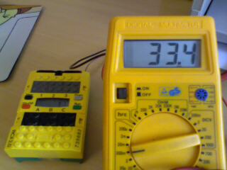
As to the power management of the RCX, we played
around with an old idea that we never developed further:
The unloaded RCX
needs around 33mA. If we disabled the peripherical devices, what
would we gain?
==> Switch off
all peripherical devices except RAM through setting H8/3292 Port5,2 pin
high.
If you are trying this in a normal program,
there is no way anymore to run your program in the external RAM. The RCX will
hang up. (If you do this with RCX 1.0 or 1.5 and display cleared, you will
need to wait about 20 minutes, before the capacitors have discharged and the
RCX will be able to reboot !!! (So, don't try it !!! With RCX 2.0, the
recovery-time is much shorter.) But, since the usual ROM function @2A62 used to power
down the RCX sets this pin high just before plunging into sleep-mode, we
assume that the external RAM maintains the data.
BUT, IF WE
TRANSFERED A PORTION OF PROGRAM TO THE ON-CHIP RAM, THE PROCESSOR COULD
CONTINUE RUNNING. ==> The unloaded, idle microcontroller needs those 33mA.The
energy economy can be improved, if all the ports are switched to
high impedance (input mode) -we will verify this with different RCX
models-, but, if we run a program in the on-chip area that regularly sends the RCX to sleep and
awakes it through the watchdog-timer
(maximum delay is 65.5ms at 16MHz) for a short time (around 10ms, the
clock-settling time included), then increment a counter as a timer and
after a while relaunch the system in order to check, if the battery-status
has improved through the solar panel charging, finally go to sleep again: we'd get an RCX that is 5/6
of the time in sleep mode with an important energy saving. The counter-timer could be
made variable, if the battery-status does not improve -during night for
instance-, so that the power-consuming RCX-functions will not be called
too often. We
are not sure about the current dissipation during sleep mode. We need to
check this.
The H8/3292 could
enter hardware stand-by mode, drastically reducing the current losses.
However, in this case the RCX can only be recovered through hardware
reset. ==> This is NOT software-usable.
==> You should run the program
with a load (a sensor or a lamp) connected to one of the sensor-ports. The RCX
will display "1234", then wait a few seconds and you will see the
display vanish. After a certain time (30seconds is indicated in the program,
but on-chip programs run faster, so it's less than 15seconds) the display will
show the inverted number "4321" and hang up in an endless loop. You
will need to take off the batteries to reset the RCX from this state.
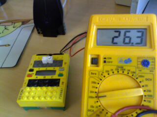
A few tests reveal that we are already able to
reduce the power consumption from 33mA to 24mA. Normal function of the RCX
drains 33mA, with the firmware
above 26mA, with the one described below,
24mA, the H8/3292 ports being configured to high impedance inputs before
disabling the peripherical devices. Note that, since the RCX has not been
initialzed, which means for instance that the main clock is not configured and
the ADC device is not active (quite power consuming ~5mA according to the
H8/3292 datasheet), the gain is not too important, if the ports are kept in
their normally configured states.
In software stand-by mode the power consumption
drops to 34mA
(micro Ampère).
==> If we manage to run an
emergency modemode with the watchdog-timer, keeping the RCX during 5/6 of the
low power time in sleep-mode, as explained above, we will obtain a minimal drain
of:
(5*34E-6+33E-3)/6=5.5mA.
... added at 18h28 !!! :
Bad news : we were NOT able to wake up the microcontroller through a watchdog
NMI generated interrupt. software stand-by mode -the regular RCX power-down
mode-, which also halts the internal clock and thus the watchdog-timer. So,
there remains the way to change to sleep mode, which is not that power economic.
2008/03/15
So the RCX microcontroller H8/3292 (former
Hitachi, now Renesas) has three different low-power modes:
sleep mode
software stand-by mode (used by the RCX)
hardware stand-by mode
These modes require different configurations and
can be excited -according to the manual- through:
internal/external interrupts, physical reset
or non-maskable interrupt on the related pins
physical reset or non-maskable interrupt on
the related pins
physical reset or non-maskable interrupt on
the related pins
The RCX uses the IRQ1 interrupt, if the On/Off
button is being pressed. Our experiments showed -and it seems soemwhat obvious-
that the software stand-by mode cannot be quit through an internal interrupt.
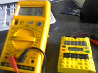
So, we tested the simple sleep mode, which halts the CPU, but does not affect
the peripherical devices nor the clock, which continues running, accordig to the
hardware manual.
The current is quite low: 18mA, under normal
device conditions and 8.14mA, if the ports are configured to high impedance.
However, through a lot of tests with
NMI, IRQs or timer interrupts, we were NOT able to wake-up the RCX from simple
sleep mode that we configured through clearing bit 7 of the system control
register SYSCR @FFC4.
??? Has anyone got an idea about how to
do this???
... added at
22h30 !!! FIXED THE PROBLEM !!!!
The issue was that we were using the
Assembler code bclr #7,@0xFFC4 in order to select sleep mode instead of software
stand-by mode. We already had troubles with direct bit setting or clearing with
other microcontrollers. Sometimes the hardware requires that certain registers
are first read and then set. This also is the case with the SYSCR register of
the H8/3292. So, we used the following code instead:
mov.b @0xffc4:8,r6L
and #0x7F,r6L
mov.b r6L,@0xffc4:8
==> And everything works now. We
already tested the NMI-interrupt that is generated through the watchdog timer
overflow and IRQ0 interrupt that is produced through the RUN-button pressed.
Here a screen-shot of the ULTIMATE ROBOLAB code.
If you run this firmware,
the RCX will fall into sleep-mode after 4 seconds (you recognize the state
through the current drop). If you press the RUN-button then, the RCX will awake
and the numbers will increment on the display, as long as you hold the
RUN-button. You will need to take off the batteries in order to reset the RCX.
from an old PC voltage regulator we could
unsolder a toroid coil of 47 [microHenry] - estimated from the torus type
and the number of turns - ; we also unsoldered an MC34063 chip.
now we will try to realize a switching
regulator for our solar panels
Philo suggests that we'd put the panels in
parallel. According to him, switching regulators don't work too well, if the
input voltage is too close to the output voltage.
We reproduced Philo's
step-up switching voltage regulator on test board with a few
differences. First we used our recycled toroid coil of 47[microH] instead of
the indicated 220[microH]. The diode is replaced with a Schottky 1N5817 and
the resistor bridge now has 15k and 100k resistors. The ratio 15/100 is the
same as 1.5/10, but there are fewer current losses. The switching frequency
is a bit increased through the use of 330pF instead of 470pF.
A diode is placed between the boost-circuit
and the solar panels to prevent backward-currents. Now we are using 3 panels
in parallel together with the LEGO capacitor.
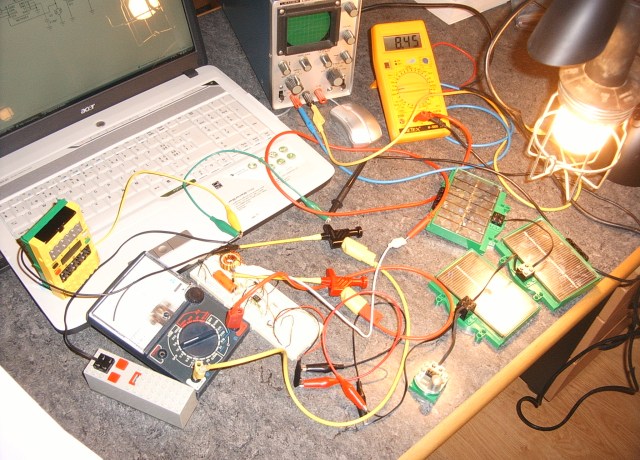
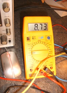
As can be seen on the picture, the tests are
made under synthetic light conditions. The device produces more than 8mA
charging current at 6.5V. If an RCX is added to the circuit together with
weak batteries, the current increases to more than 15mA, but the voltage
drops to 6V. With almost full batteries the charging current diminishes to
3mA at a voltage of 7.5V. There doesn't seem any risk of overheating. BUT, A
LONG-TIME TEST IS NECESSARY TO VERIFY THIS.
We now will turn towards redesigning the rover.
"Electronique
Pratique" issue 269 (Oct. 2002) completely was dedicated to
switching voltage regulators (French electronics journal)
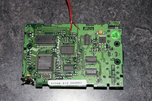
Here now the general overview of the rover's
electric devices.
There are 2 RCXs. The right one will serve as
the master, keeping connection to the PC via infrared channel (and the
infrared/RF repeater system that we developed for Mars
mission B.) It also will be responsible for the control of a simple low
size camera module that we bought from electronics123.com.
First the RCX will provide the camera's supply voltage (=3V3) through a PWM
signal on Port B. The voltage will be controlled through RCX Input 2. A
capacitor will be added to the camera (not indicated on the
picture!). The RCX also provides a bit-banged serial duplex communication to
the camera. The camera's TX line must be cut-off from the RCX 5V (Port
1) through a resistor/Zener diode bridge. The RX line is connected to
a pull-up resistor. The RCX Port A will toggle between brake and float mode,
which acts as a simple switch. We successfully played with this unorthodox
use of the motor port. However a protecting Zener
diode should be added to prevent accidental damage of the camera.
Port 3 will monitor the temperature of the robot's motors. Port C will
shortly flash a lamp that will then drive a phototransistor, pulling down
the RUN-button H8-port of the left RCX in order to generate a hardware
interrupt capable of waking up this RCX, in the case it went to software
stand-by mode. (The green RUN-button will be taken off to allow access to
H8/Port4,2. The button will be configured exactly as the ON/OFF button if
the RCX goes into stand-by mode. It can be awaken from sleep through a short
light flash or pressing the ON/OFF button)
The left RCX will power the infrared/RF
repeater through Port C. Otherwise it will control both driving motors, the
bumpers and the rotation sensor. Note that the light sensor will share Port1
with the right bumper.
The battery packs of both RCXs will be
connected in parallel. Both will be wired to the 9V boost voltage regulator,
which is served by the solar panels and the LEGO capacitor.
Both RCX will communicate with each other
through the infrared channel using the 0xF7 opcode that does not produce any
PC reaction. The slave RCX to the left will not answer any PC request - any
other opcode reaction than 0xF7 will be turned off. Master RCX will be able
to answer to a few PC-requests, among which memeory polling, that is
necessary for upload of a picture that the camera has taken. The main
mission of the master RCX, besides the power management and the
communication with the PC, is the camera control.
Elektor
also has an issue that is dedicated to switching regulators (Issue 409
Jan. 2005 - German)
Elektor
published a journal completely destined for robot building (Issue
Jul/Aug. 2007)
The solar cell consists of seven (7)
solar cells and a diode. They are connected in serial so the total
volt = 7 x 0.4 V (a total of approximately 2.8 V).
3 V, 200 mA at full sun outdoors
3 V, 100 mA at full sun indoors
through window
2.5 V, 8 mA with light from 60 W
incandescent lamp with 25 cm distance to solar cell (2000 lx)
2.5 V, 40 mA with light from 60 W
incandescent lamp with 8 cm distance to solar cell (10,000 lx)
Lego also offer the following cautions for its use:
The solar cell is not waterproof
Do not bend excessively or push hard
on the clear plastic window
Do not step on or otherwise place
heavy weight on the solar cell
Ordinary incandescent lamps produce
a lot of heat and should only be used for short periods and at a
distance of at least 8 cm
2008/03/27
The C323-7640 camera should be driven between
3 and 3.6V. Typical operation current is 60mA.
Since energy economy plays an important role
in this project, the supply voltage for this device should be obtained with
the fewest losses. Normal linear technology would regulate the voltage down
from the 7.2 - 9V that an RCX output port can deliver. However about 0.5W
would be lost in the regulator.
An alternative could be a buck step-down
regulator that is comparable to the described boost regulator.
Another alternative could be the use of the
RCX PWM mode that is disponible for each output port. The idea is to have a
direct feeback of the voltage to an RCX input line and have a control-loop
regulate the output power.
Here our design:
Diode D1 prevents the device from bad
polarity. C1 and C2 are needed to filter the PWM-signal and also damp
oscillations that might be generated through the software regulation
process. R1 (10Ohm) limits the current through the Zener-diode D2. The
resistor bridge is needed in order to allow valuable measurements through a
passive RCX input port. Note that there is a small difference of voltage
between an RCX output port and the RCX ground, because of the internal
switching transistors. In order to prevent short circuit in the case of bad
polarity, we added R4 between the device 0V-point and the RCX ground.
Note that the capacitors have been chosen very
large. This is necessary, because of the variable PWM frequency provided by
ULTIMATE ROBOLAB (30..500Hz, depending on the power level) and the
comparably high current.
The resistor bridge R2/R3 must be considered
with the RCX internal sensor input pull-up resistor:
The regulating RCX software
control must then try to maintain this sensor value constant.
Since power-levels are not proportional to the output voltage and the
slope of the function is steeper at low power-levels, the sensitivity of the system is more important at higher battery levels.
Examples: (3,3V Zener disconnected)
1. If the RCX is powered through the AC-adapter, the battery voltage rises to 9.8V, and the power level varies between the values 30..33,
producing a voltage swing of 50mV amplitude.
2. If the RCX is powered by weak batteries and the main voltage drops to 6.9V, the power level varies between 71 and 72, with a resulting voltage
oscillation of 10mV amplitude.
Note that if the Zener diode is connected, the amplitude of the oscillation is reduced by factor 10.
2008/03/31
The serial communication with the camera can
be done at different baud-rates from 7200 to 115200. We will now try to
establish a 9600bd connection between the RCX and the camera without hacking
the RCX. The first step is to design a software RX function.
ULTIMATE ROBOLAB allows the access to the
digital input values of the RCX sensor ports. These values can be read at
incredible speed compared to the rather slow ADC acquisition.
We will poll the sensor port in order to wait
for the first falling edge that indicates the beginning of the start bit.
This requires a disabling of all the interrupts, in order to make the
reaction fast enough. At the falling edge the H8 timer0 (normally used for
sound generatiion), is configured to generate an interrupt after
1/9600+1/19200 seconds. This assures that the first bit is read in the
middle. If the first interrupt happens timer0 is reconfigured to generate
interrupts after 1/9600 seconds. Each bit is added to the serial buffer with
the help of the OR-function and bit shifting.
One issue with this software
approach is that the normal RCX functions are disabled during
data-reception. How will we be able to assure the voltage regulation control
and the infrared communication? We will probably need to write a completely
new main engine for the RCX. Hmmm!
We wondered why we need to shift the receive
buffer byte 8 times, instead of 7. (In yesterday's program it's indicated
that the receive byte is shifted 7 times, but in fact shifting is done 8
times.)
We had to better understand the timer0
interrupt. The H8 datasheet says that with the given configuration, the
interrupt happens on CMIA (compare-match interrupt request A). We thought
that once the timer-counter (TCNT) reaches the value in the TCORA-register,
an interrupt is generated. This seems to be only indirectly true. As we
interprete the interrupt triggering, the action is a bit more complicated:
the H8 clears the TCNT-register, if the value matches the TCORA-register,
but not the matching itself generates the interrupt, but the clearing of
TCNT.
Since we "manually" clear the
TCNT after the first falling edge, an interrupt is triggered as soon
as the timer interrupt is enabled. (ULTIMATE ROBOLAB uses start/stop timer,
which is not correct either, because timer0 TCNT is constantly incremented
and it is only stopped through clearing the 3 lower bits of TCR and not
through disabling timer0-interrupts.)
2008/04/02
We tried to decrease the pause between byte
sending. Assumed, the camera sends data with only 1 stop-bit, it is
necessary to verify framing errors.
==> :-( Valid bytes have
to be stored into a buffer. But, with no means we were able to do software
receive and storing under these conditions. So, we reduced the speed to
7200baud, an unusual rate that the camera supports. But,... no way to do the
job with only 1 stop-bit without repeated framing errors.
==> without hacking the RCX serial device (as
we did for the CMUCam2), there is no way to communicate with this camera.
2008/04/05
This brought us back to the CMUCam2 module.
This device consums a lot of power, but with a good power management we will
balance the gain and the losses -hopefully.
The idea is to have the camera sometimes snap
a picture from Mars and send it via radio to the "Earth" station.
This has often been done. But, since this project has educational goals:
learn about serial communication
explore picture frame encoding
"make your machine work"
use what you have
hack if necessary, but only then
etc
..., we want to have the RCX do the camera
control and the communication jobs.
With ULTIMATE ROBOLAB we could write an RCX
firmware that would start the camera, that is powered by RCX output C, in
white balance mode for 12 seconds, then switch to autogain mode, reduce the
picture size by factor 3 in both dimensions, set raw transmission ode and
send a frame to the RCX. After having sent all the commands to the camera,
the RCX would wait for valid serial data message and then power down the
camera to recover the infrared channel in order to be able to send the
picture data to the PC on request. Note that the camera interface
electronics allows to use the RCX serial channel either for the camera or
for the normal RCX infrared communication.
Here the UR program: Note that we fixed a
small bug in the Begin_advanced_serial.vi (non_LEGO_serial.llb): the
serial_timer_control task needs the "Large constants" modifier for
the timeout constants, otherwise the program will wait the full timeout,
even after having received the frame correctly. Also note that the CMUCam2
frame packet has the following aspect:
Although the program is in raw mode, the
acknowledge is sent in ASCII code with linefeed. The "1" indicates
the beginning of the frame, the "2" announces the end of the line,
the "3" shows the end of the frame.
The picture size isn't famous
yet, and the transmission to the PC lasts quite a long time, but... we do
everything with RCX !!!
Here some details of the picture
data. Note the end of line "2"s.
We will now propose a very simple way to awake
an RCX from deep software stand-by mode. By contrast to the idea expressed
in this journal on March 26th, the RCX will receive a
parallel possibility to shut down or wake up that may be done through a
bright light flash.
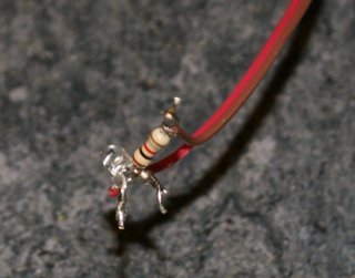
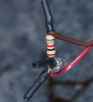
The trick is to solder a BPW42
photo-transistor in series with a 1k resistor between the contacts of
the RCX On/Off button. Even under ambient light, this photo-transistor has
quite a high impedance. Only very bright light flashes that are directed to
the lens of the photo-transistor are able to draw enough current to trigger
the On/Off interrupt. This assures that the shutting down or switching on
are not activated by spurious light impacts. Even long range IR-transmission
doesn't produce any reaction, unless the IR-beam isn't very close to the
photo-transistor.
Later, the master RCX will receive a
flash-light that will switch on the slave RCX after hibernation.
Btw, taking photos with a flash-light triggers
the On/Off interrupt.
 4th edition


 (enlarged)