 (Source: http://www-date.uni-paderborn.de/pub/people/dasas/Beh03.pdf)
Directly connecting a digital camera module to the RCX
JOURNAL (very long)
last update 16/07/05 : a movie showing a mobile color tracking robot !!! (see below)
created 15/04/05
This will be our ambitious project for the next months, and we are not certain at all that this time we will succeed.
If we look over the web, we must conclude that only very few LEGO robots have been realized that use the LEGO camera. This might be a matter of price. (Our LEGO parts provider Technik LPE in Germany now sells it for about 30.- only !) But the reason for this could also be the fact that the autonomous LEGO robot is no longer autonomous, since the camera is wired to the PC.
The challenge is to directly connect a digital camera module to the RCX and implement some simple picture analysis into the LEGO brick to have a visual robot. We already produced lot's of sensors around robot ears. Now it is time to try this. But, honestly, we are skeptic.
The module
The C3088 is a 1/4'' color camera module with digital output using OmniVision's CMOS image sensor OV6620. The module is known from the excellent CMUCam2 device. Some features :
The data is put out via Y digital bus or/and UV bus. There also exists a monochrome composite video signal output, useful during test phase. More information at http://www.ovt.com
Provider : http://www.roboter-teile.de (Thanks to Mr. Jörg Pohl)
A similar project has been developped by Iñaki Navarro Oiza (LTH-Lunds Tekniska Hogskola, Sweden, May 2004) http://www.robozes.com/inaki/dproject using an AVR microcontroller.
A first overview of the module datasheet reveals :
I2C communication with the RCX
State of art :
What do we need:
Brain-storming:
18/04/05
A well placed message posted to Lugnet always generates some interesting reactions:
As to hardware hack, there are two pins on H8 port 7 that are unused in the RCX. It seems that they are tied to 5V through pull-up(s?). These could be used too.
Conclusions :
==> We have gathered information about the IR-communication during several projects, especially the IR/RF repeater system, and we learned how to operate the IR channel. Setting up an IR/I2C system should not cause any problem. Thus, we will probably develop such a system on our own.
30/04/05
The C3088 module communicates the digital picture data via parallel bus. This IS the major problem, because the RCX has only three input lines available. The only solution would be to add another microcontroller that should manage everything : I2C bus, the IR-channel and the parallel busses IN and OUT. We would then have the microcontroller acquire the digital picture data at 277kHz, filter / average it and send the data out through a R/2R resistor net to generate an analog signal at less than 55kHz, which is the fastest analog sensor reading rate that we can obtain with the RCX (reading and storing). This serialization also would need horizontal and vertical synchronization pulses that could be obtained through shortly setting 0 or 255 values that don't appear with the picture data, since the camera only returns color level values from 16 to 240.
Operating picture analysis in the RCX with reduced picture data could be rather easily implemented. It's only a matter of optimal algorithms. But, the data-transmission problem requires at least a PIC 18F452 to reduce the data without gain of information about objects, positions, directions or motion.
==> CONCLUSION: this project solution isn't worthwhile, because of the costs in terms of loss of information, material and work !!! Setting up the I2C is already complicated, but transmitting bad digital picture data to the RCX is beyond good reasoning. So, we will try to obtain the CMUCam2 module at about 90.- . This module communicates with external devices via serial channel, which is very easy to do with the RCX. The module works with a DSP-chip and has many built-in picture analyzing features. By this way, the RCX only gets pre-processed data. Information is converted, but not lost.
10/05/05
Serial communication with the H8/3297
The CMUCam2 module arrived quickly from our provider Roboter-Teile.de (Thanks Jörg Pohl for the help.) We are amazed about the features. There is a easy-to-use GUI running under Java 2, which is distributed in the package. Every detail is documented: circuits, chip-datasheets, software etc. Really cool !!!
Connecting the camera to a PC is rather simple via serial port. We tried Hyperterminal to send single commands and get byte-streams. Everything works fine.
Now to the serial connection towards the RCX: we cannot use the IR-channel, because the local echo on the IR-channel would produce garbage in the CMUCam2 module which works in full duplex mode. So, we have to hack the RCX this time and forget about our rule saying that our RCXs should be kept untouched !!!
A student at Universität Paderborn did that to set up a bluetooth-connection. (Very impressive !!!) He unsoldered the H8/3297 TX and RX pins and wired everything to a miniature sub-D connector :
(Source: http://www-date.uni-paderborn.de/pub/people/dasas/Beh03.pdf)
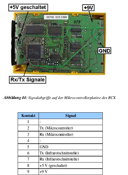
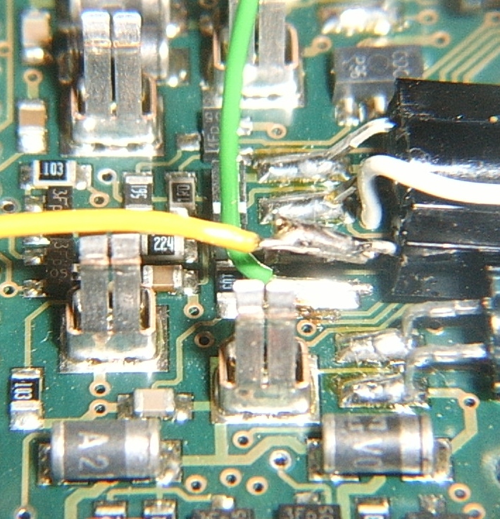
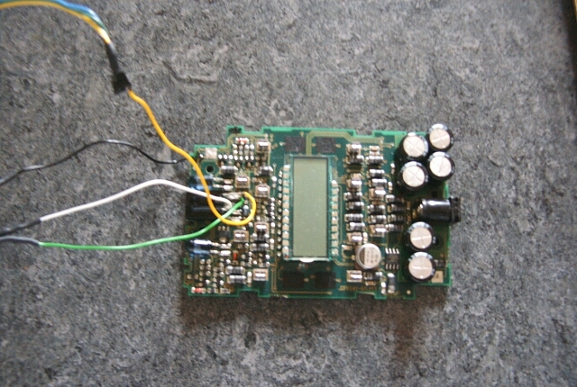
Another (easier) way to attack the H8 serial port directly is to unsolder the data pin of the IR-receiver and to solder wires to better accessible PCboard pads:
|
|
|
|
|
|
|
|
|
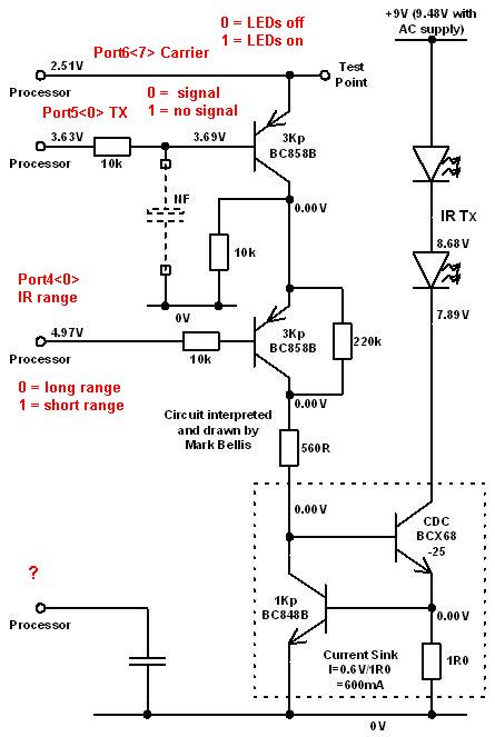
|
Source : Mark Bellis / changes (red) Claude Baumann |
|
11/05/05
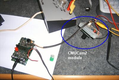
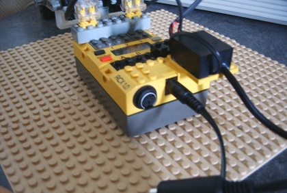
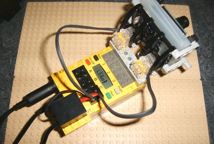
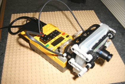
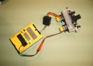
The workbench ! Note that we fixed the CMUCam2 module into an old Ninento Game Boy cassette box.
This Ultimate ROBOLAB test program is very low level and has the following functionality:
Note that the new serial TX and RX drivers for the RCX communicate with each other through a variable called IR_state that can have 4 different values:
The CMUCam2 module must now be prepared:
Wow !
The CMUCam2 module answers correctly. This is really cool !
We first were frightened, because the display started with the ASCII value 58. But then appeared the rest of the sequence : 13 / 75 / 67 / 65. If we translate to characters, we have the code " :\rKCA ", and since the RCX-program puts out the data in reverse order, this is the expected CMUCam2-reply " ACK\r ", however followed by a " : ".
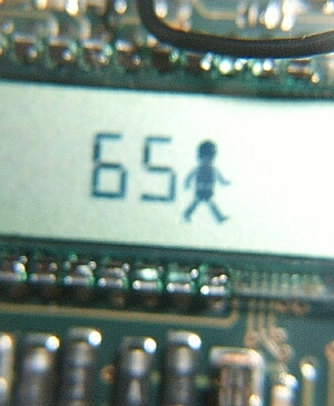
The last put out code is very important, ASCII 65 = character "A". This is the reply for the correctly received and interpreted byte. Otherwise the CMUCam2 would send an ASCII 78 = character "N" - " NCK\r: " (not acknowledge !)
==> Now things have to be refined:
20/05/05
Now it is the time to realize a perfect interface between the CMUCam2 module and the RCX that would have the following features:
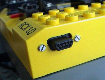
Unlike the Paderborn example above, we will use a DIN connector (PS/2).
ATTENTION : don't connect a PC serial device to the RCX. Don't use a null modem cable with the PC. This will damage the RCX !!!
![]()
If we want to use an RCX output port to power the CMUCam2, we must pay attention to the ground (GND). If an output is set to forward direction, +9V will be located on the left side of the LEGO connector. -V will be found on the right side.
In fact there is a 0.3V difference between RCX GND (shield) and the -V pin. Philippe Hurbain (one of the best Mindstormers) explains that this voltage is due to the RCX H-bridge that powers the output ports. However there should be no problem to connect both pins, because one lower H-bridge transistor will be simply short-circuited without any damage. But, attention should be paid not to inverse the output direction. Otherwise the bridge will be short-circuited to GND. To prevent any damage to the RCX in that case, we must add a 300-400mA rapid fuse between GND and -V.
To prevent damage to the CMUCam2 module, we add an 1N4002 protecting diode.
Also see: http://news.lugnet.com/robotics/?n=24002
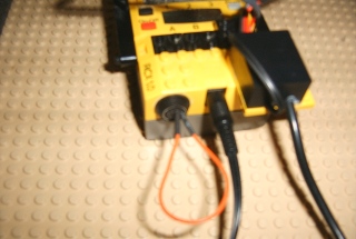
The interface looks like:
How does it work ?
How the raw connections look like:
![]()
Already improved !
We now test the device:
1. Does the camera work correctly?
First, in order to allow the RCX to load a new firmware, the RX-pin and the IR-receiver data-line must be short-circuited.
Before running the following program, remove the wire and plug in the PS/2 connector.
In the program-diagram there are several new sub.vis, explained below :
|
|
Container holding the serial state; may have the values : IR_ready (0), IR_receive (1), IR_RX_valid (2), IR_transmitting (3) |
|
|
Value indicating the received data size [bytes]. |
|
|
Begin advanced serial : initializes the serial communication. |
NOTES:
2. Does the RCX infrared channel work correctly?
We add the following code to the red marked place in the program above. This will cause the program to switch back to standard infrared serial.

23/05/05
Next step: continuously send a "Get Version" Command to the CMUCam2
The CMUCam2 datasheet specify that a GV\r should return the string "CMUCam2 v1.00 c6\r". The test-program is altered a bit to allow sending a series of bytes instead of a single one. Note that the serial states are recalled "serial_ready" ... instead of "IR_ready". A new state is added: "RX_buffer_overflow". Baud-rates may now be set to the values 2400, 4800, 9600, 19200. The current serial state is displayed in the right-most digit.
The camera returns the correct strings:
ACK\r
CMUCam2 v1.01 c6\r: (Note new version number)
However, 1 packet of 5 is bad-received. Erroneous bytes always are located at (red marked), never anywhere else :
ACK\rCMUCam2 v1.01 c6\r:
After numerous tests including:
the result always was the same. Some speculations about the origin of the problem:
==> one part of the problem seems to be the fact that the serial state was cleared from "serial_transmitting" to "serial_ready" too early BEFORE the disabling if the TX-device. Thus in some cases the device-disabling could have happened during the receiving procedure and this affected the correct receiving !!! SOLUTION: clear the serial state only after the normal TEI-interrupt handling.
We have a drastically improved communication : only 1 of 20 packages are erroneous anymore. Problems could still be other RCX interrupts that are triggered exactly between the sending and receiving procedures.
==> Conclusions:
27/05/05
Since we are moving from the serial layer to the CMUCam2-module command layer, it is a good idea to use the ROBOLAB/LabVIEW feature to create new sub.vis from lower level code. We therefore first create a send_command function that replaces an extends the send code above. The idea is to have a sub.vi that is able to communicate CMUCam2 commands in string form. To distinguish the allround 0xD ASCII (\r), we use the LabVIEW "\" displaying format. We also engage a semaphore to prevent different RCX tasks from producing access-conflicts to the global array "command".
Now the test program has a much better appearance: (Note the new serial state : "serial_disabled" which cannot be cleared by the watchdog)
29/05/05
Now we are reaching another test-phase, where the CMUCam2 module features will be explored. There was a discussion, whether to build a subroutine with parts of CMUCam2_send_command.vi in order to reduce code size, because of multiple calls of that sub.vi. However the gain would be insignificant, because a function would be necessary rather than a simple subroutine, since then the length of the command must be passed to the function as a parameter. Instead the semaphore has been removed. So the user must pay attention himself and add semaphores, where he desires to avoid conflicts.
Here a first test to track a color (Note the new Begin icon called CMUCam2_init.vi which includes the option to power the cam-module via RCX port C / default TRUE) :
The CMUCam2 set includes an exhaustive documentation. The device is really easy to manipulate, once the serial communication is set up correctly. Note that this time the tests are made at 4800 baud. (For better readability, the LabVIEW normal string display was used. ATTENTION: LabVIEW considers the "return" key as "line-feed (LF or \n)" with ASCII value 0x0A. Perhaps it is a good idea to add an option to automatically add CR ( \r ) and replace LF with CR.
31/05/05
Repeated instructions can be simplified a lot. So that's the new TX sub.vi. It is made polymorphic. This means that LabVIEW will automatically choose the right sub.vi at a lower level, if the user either adds a single string or an array of strings. Note the new "Begin" icon -only cosmetic changes :
This leads to the more refined, where you add simple parameters to the sending sub.vi. So, things are made rather simple. For instance, the tracked color can either be entered as a RGB-long-integer or a real color selected from a palette. This reduces the program to a minimum :
For those who are interested to have a look behind the scene :
Here the serial stuff in one shot :
03/06/05
On this base, the CMUCam2 access can be simplified even more. The result will be very user-friendly programs. The sub.vis have been submitted to some minor changes. Now the second icon includes waiting for ACK after a CMUCam2 command and a continuous data-extractor task. The octagonal icon stands for an U8 container with the selected name :
The RGB-color can be selected by clicking on the red square. LabVIEW color palette appears, and the color is adjust through mouse move and click :
The extractor task :
The serial stuff has been updated :
04/06/05
See the nice color tracking robot video.
The RCX runs the following program :
21/06/05
The serial stuff has been extended to include a new packet marker. In fact, as already pointed out, with the CMUCam2 module it might be utile to switch to a kind of raw mode, where the CMUCam2 sends data in byte format rather than in string format. This reduces the packet sizes. But a new difficulty appeared during the tests. Since there is no terminating string anymore, the packet where distinguished through the packet length, which means that the program waits for a certain number of bytes that must arrive during a fixed time. Now, if the timeout is not well chosen, and a byte is lost, the RCX would get correct bytes, but wrong packages, because the bytes were considered in a bad order.
Example:
A reduced T-packet (only Mx and My values) would look like in raw mode:
255 54=ASCII(T) 40 36 / 255 54 41 35 / 255 54 41 37 / ........ and the application would consider :
Mx(1)=40 My(1)=36 / Mx(2)=41 My(2)=35 etc
Now, suppose a byte being lost on its way for any reason. The series would receive another appearance, since the RCX would arrange packets differently, always waiting for 4 bytes:
255 40 36 255 / 54 41 35 255 / 54 41 37 255 / ...... and the application would necessarily interpret :
Mx(1) =36 My(1)=255 !!!!! ERROR
It is therefore essential to respect the value 255 that the CMUCam2 sends for synchronization purpose. (No following value in the packet ever is 255 !!!)
So, now the serial stuff is able to reset the packet index every time the start marker appears. If a byte is being lost, there would of course be one lost package, but the following packages would return to the correct rhythm !!
The RCX now also is able to extract CMUCam2 S-packets that give information about the average color values and the standard deviation. Here a program example :
Actually the application layer set is composed of the following sub.vis :
|
|
Initializes the CMUcam2 module, implements the non_LEGO_serial.llb, handles communication layer, initializes RCX with standard Ultimate ROBOLAB kernel |
|
|
Configures the CMUCam2 to track either a given color or a window from which the camera extracts the color that should be tracked. Includes white balance, auto-gain and noise-filter options. Returns T-packets. |
|
|
Configures the CMUCam2 to return S-packets with information about the picture averages concerning RGB colors and the respective deviations. |
|
|
Enables or disables the white balance. Option to allow at start only for 12 seconds, then turn it off. Select a different color space: either RGB or CrYCb |
|
|
Enable or disable autogain. |
|
|
Activate noise filter. |
|
|
|
|
|
|
There was a bug in the CMUCam2_RX_T_packet.vi, index was bad :
16/07/2005
There have been many questions about our project. Here some answers and changes !
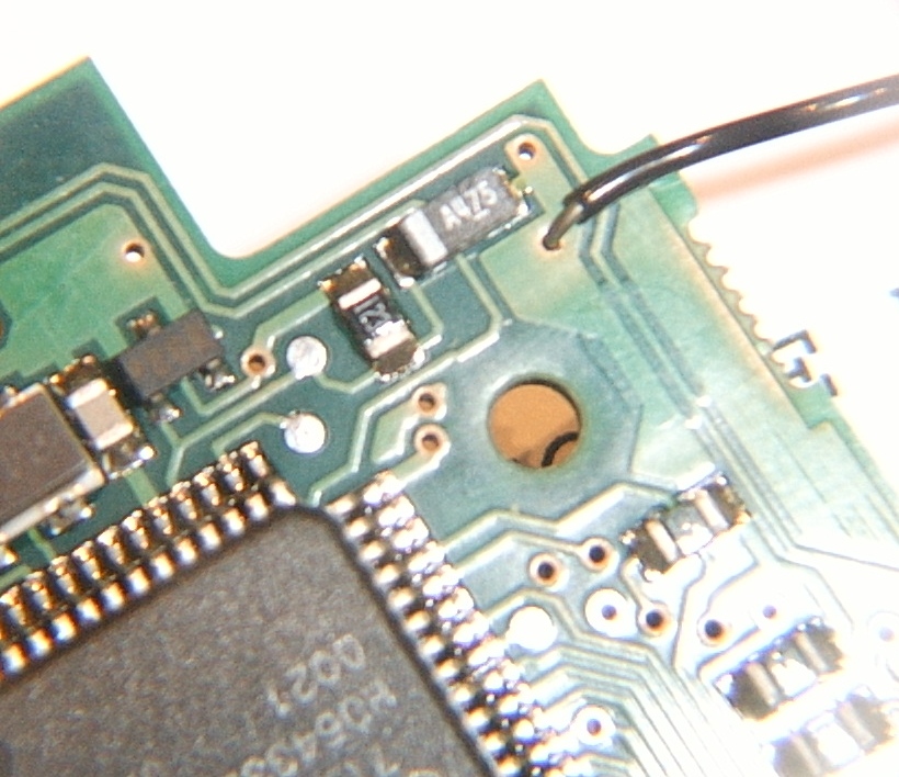
1. QUESTION: where do we find stabilized 5V on the RCX board ?
ANSWER:
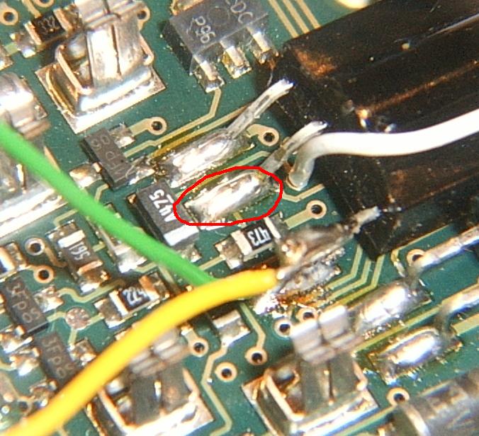
The easiest way to connect to the RCX stabilized 5V supply is to choose the middle pin of the TSOP1138 infrared receiver. Note that the 3d (upper pin on the picture) is Gnd.
2. QUESTION: the interface to the CMUCam2 module is cool, but is there a possibility to avoid the nasty wiring, if the module is not connect?
ANSWER:
Yes, if we add a 1M resistor to the interface. Here the new schematics and an smd-board. (Note that we couldn't find a valuable smd PNP transistor, so the 2N2907 is traditional package.) Now things are even made easier. We don't use any connector for the second edition, but keep the small device wired. Now there is no problem anymore. The RCX will be able to do infrared communications either with CMUCam2 connected or disconnected.
 RCX
to CMUCam2 interface 2nd edition !
RCX
to CMUCam2 interface 2nd edition !
By contrast to the following schematics, the power supply for the camera on the photo doesn't pass through the interface.
Note that the fuse has been replaced by a 47Ohm resistor. (Should be 2W, but we chose 1/4W which will probably become very hot, if the polarity on PortC was reversed... we didn't try it !!)
The board needs 2 additional wires (yellow on the PCboard diagram !!!)
3. QUESTION: Where do we find the Ultimate ROBOLAB files to control the camera?
ANSWER:
Right here ! Note that actually Ultimate ROBOLAB is being beta-tested. Please contact the web-master, if you are interested in participating. The CMUCam2 module requires UR version 1489.
to be continued