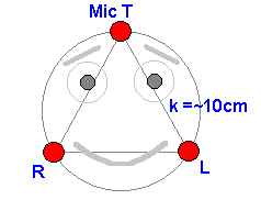
 R(ight),
T(op), L(eft).
R(ight),
T(op), L(eft).Hearing
Localizing a sound source in space
last update 03/02/03
GASTON, our major project of 2002/2003 is equipped with a performing sense of hearing. Thus GASTON is able to find the origine of a pulsing sound source. Here now the detail of this sensor:
1. Basics
 R(ight),
T(op), L(eft).
Our former phase-sound sensor was able to fix a noise-source in two dimensions. This was done through a precise measuring of the delay between the impacts of the sound-wave at two different microphones. We now extend the system by adding a third microphone.
The noise localization is yielded by estimating a horizontal angle a and a vertical angle b. Since the segments [R,T] and [L,T] are not orthogonal to [R,L], we suppose that b might be estimated through one of both bR or bL which are the extracted angles of the operations RT resp. LT. These operations are done similary to the following, where a is computed in operation RL. bR is chosen if the sound-source is situated to the right. bL is selected in the other case.

soundvelocity: c = 343m/s
2. Test device
Before exploring more deeply, let's have a look at our test device.
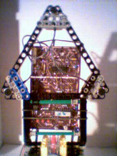
The device is equipped with a PIC 16F628 which returns three integer time-values R, T, L via infrared channel - note that RTL is also the sending sequence -. To be precise, the device remotely sets RCX-variable 0 (red) to R-value, variable 1 (blue) to T-value and variable 1 (yellow) to L-value. It therefore uses the LEGO-IR protocole. By this way the RCX, or for instance the LEGO USB-tower, receives the time-data of the actual sound-wave.
Example:
NOTE: the device is clocked at 20 MHz, which provides a timer increment at 1:1 of 2E-7sec. (A timer-increment happens every fourth clock-pulse.)
In our case the microphones are equidistant with k=10.8cm. So the maximum delay is:
tmax = 10.8E-2 / 343 = 3.149E-4 sec = 1574 time-units
Now we are able to deduce q in the formula above related to our particular time-unit. At 90 we have a maximum delay of 1574 U. Thus:
q = 90 / 1574 = 5.718E-2
Here the principal formulas :
a = q * ( R - L ) bR = q * ( R - T ) bL = q * ( L - T ) IF a>0 then b = bL else =bR |
3. Test program
For better control and calibration, the device has been equipped with three LEDs which are alignated in the RTL-order. They flash in the order of wave-impacts. At the end of the video you remark another flashing LED. This is in fact the IR-LED communicating the data to the RCX or the LEGO-tower. (Remember that the LEGO-camera, which took the pictures, is IR-sensitive.)
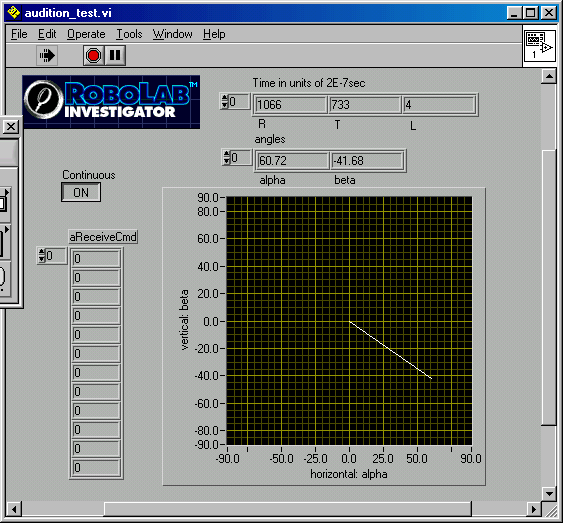
In advanced ROBOLAB we created the following program, making visible the directions towards the sound source. Note that t0 is never zero. This is due to PIC 16F628 computations. The PIC-program registers additional 40 time-units in the case of synchronous wave-impacts. The precision of the device is therefore reduced to 40 * 90 / 1574 = 2.28°.
4. Schematics
(Note: We thank our friend Mr. Jean Mootz for preparing the two-sided PCboard. Those who are interested in more schematics details and the PCboard may contact the web-master.)
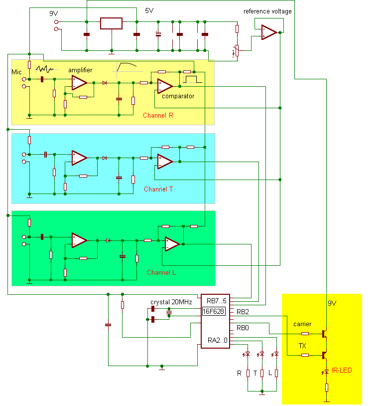
In the schematics a power-supply part may be distinguished with adjustable reference-voltage for the comparators. The potentiometer allows sensitivity calibration. You recognize three identical microphone-amplifier-comparator modules for the three channels. The channel outputs are connected to PIC 16F628 input pins. If at the channel-entrances the signal-voltages get higher than the reference-voltage, the comparators consecutively switch from logical 0 to 1 in the order of phase delays. The PIC registers the order and the time-data.
The infrared sending part is made of two transistors, three resistors and an IR-LED. The transistor-basis are controlled from the TX-pin (RB2) of the PIC's UART and pin RB0 which transmits the 38kHz carrier.
The TX-stand-by voltage is 5V. This blocks the PNP-transistor. The IR-LED emits only if both transistors are conducting.
5. PIC-program
We have prepared the PIC16F628 program in a special unofficial and unpublished ROBOLAB-part created here in sept/oct 2002. (Credits to Prof. Chris Rogers from Tufts University). Some program-extracts to illustrate the procedure:

The IR-sending sub.vi follows the LEGO protocole explained at the Broadcasting-page and the multi-robot page. What is interesting here is the way we are producing the IR-signal. Every byte is sent through a three-part sequence:
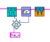


In Cycles2.vi the FOR-instruction needs 3 PIC-cycles, each SETPORT needs 1 cycle, the ENDLOOP has 2 cycles, each CALL has a 1 cycle duration.
Total: 9 cycles = 9 * 2E-7 = 1.8E-6 sec
We want the sending frequency to be 38kHz. The periode is 1/38000.
==>PAUSE = ( 1/38000 - 1.8E-6 ) / 2 = 1.2258E-5 sec
The UART sends 1 start-bit, 8 data-bits, 1 parity-bit, 1 stop-bit = 11 bits
At 2400baud 11 bits need : 11/2400 = 4.5833E-3 sec
==> number of 38kHz cycles for the sending of 1 byte: 4.5833E-3 * 38000 = 174.1 cycles. We got the best result with 200 cycles, since there is a small pause between the sending of two bytes.
As we are setting three RCX variables, we use the RCX opcode 0x14, which is 15 bytes long (with header, complements and checksums). Since the opcode is constantly repeated, the fourth opcode-bit must be toggled according to the LEGO protocole. The PIC does not verify the RCX-replies. So, we are never sure whether the toggle-bit is expected to be set or to be cleared. The opcode is simply sent twice, once the toggle-bit cleared, once the toggle-bit set. By this way, the data must be accepted by the RCX. Between the sending of one opcode, there is an additional 200ms pause.
Transmission-time: 3 * ( 2 * ( 15 * 200 / 38000 + 0.2 ) ) = 1.67 sec
This is OK for the purpose.