|
created
2008/03/16 last update 2010/01/28
==> NEW
Kalman
Filter with indoor GPS
|
some links:
- old
Convict beacon projects
- Höhrmann's
project (German)
- Höhrmann's
slides (German)
- Positioning
with Independent Ultrasonic Beacons
- The
Cricket Indoor Location System
- Optimal
estimation of position and heading for mobile robots usingultrasonic beacons
and dead-reckoning
Kleeman, L. Robotics and Automation, 1992. Proceedings., 1992 IEEE
International Conference on Volume , Issue , 12-14 May 1992 Page(s),2582-2585,vol.3
-
A
Simple Ultrasonic GPS System for Indoor Mobile Robot System
using Kalman Filtering,
SICE-ICASE, 2006. International Joint Conference, Oct.
2006, 2915-2918
|
|
2008/03/16
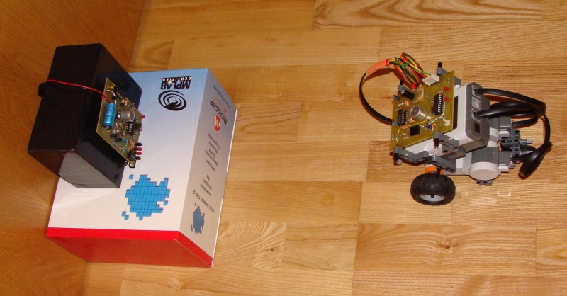
It was time to bring one of our most ambitious projects to the NXT level. We
remind the main idea, which is to have a GPS-like system composed of several
beacons that send out infrared signals together with ultrasonic bursts. The
infrared flash of a single beacon almost arrives instantaneously at the robot
that is equipped with a combined infrared/ultrasonic receiver. But the ultrasonic signal
only arrives with a
certain delay, due to the "slow" sound velocity, in comparison to the speed
of light. The receiver is able to measure the time lag between both signals and
deduce the distance between the robot and the beacon.
The main issues with the previous
devices were:
|
|
- accuracy was
limited to about 4cm
- multi-robot
applications weren't possible
- neither the
IR-sender nor the ultrasonic transmitter were optimal in terms of power
efficiency, with the result that the system was too much directionally
sensitive and thus could not be used in larger rooms
- synchronization
between the beacons was too difficult and needed several RCXs
GENERAL DESCRIPTION OF THE NEW SYSTEM:
- indoor robot
navigation
- allows multi-robot
localization
- error less than
1cm
- low current
dissipation
- tested over a
range of 10 meters
1. BEACONS
- participation of
up to 7 beacons that may be placed at strategically interesting places
- the beacons send out strong IR and ultrasonic signals that don't require
reflectors on the receiver side
- like RF-beacons,
these beacons transmit their identification number, making localization easy
- always one beacon
acts as the master beacon, sending out a synchronization message to all
other slave beacons
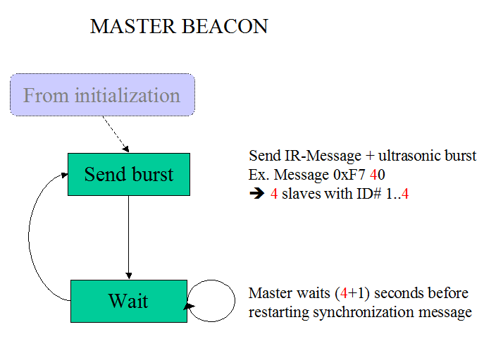
- the master beacon
with system ID=0 transmits out a standard RCX compatible IR 0xF7 message. The
lower nibble of the message-value is Master_ID#
= 0. The higher nibble is the number of participating slaves N_s.
(Example: If there are 4 slaves, the message-value will be 0x40.) Note
that the beacon doesn't expect any reply on 0xF7 messages, as it also is
the case with the RCX.
- After successful transmission of the IR-message, the master-beacon sends out a short ultrasonic
burst of 1.25ms duration at 40kHz. Now the master waits
(N_s+1) seconds before
restarting the procedure.
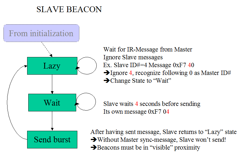
- Then the system
waits exactly 1 second, after which the first slave sends out its 0xF7
IR-message. The message-value now is Slave_ID#
= 1. After correct IR-transmission, the slave produces a short
ultrasonic burst.
- The beacons are
jumper configurable. (One jumper defines whether the device acts as the
master, the other three jumpers set the Slave_ID# or
in the case of the master the number of participating slaves N_s.)
- Each beacon is equipped with an infrared receiver (obsolete in the case of the master). If
the slaves receive a master-message (with low nibble 0 and high nibble
<>0), the slave calculates its wait-time before being able to resend the
signals. (Slave1 must wait 1 second, Slave2 waits 2 seconds and so on.).
This procedure guarantees that the master beacon synchronizes the whole
system. (The pause between sending, now being 1 second, could be reduced in a future
firmware with a lowest limit of 35ms needed for sending the 0xF7 message
composed of 9 bytes plus the ultrasonic burst.)
2. RECEIVERS
- Any participating
robot must be equipped with a receiver. There is no limit for the number
of receivers, because the receiver-devices do not interact.
- The receiver is
NXT-compatible. It is powered from the NXT and is configured as aa I2C-slave,
answering to NXT requests.
- If a receiver gets
an infrared identification number message from on of the beacons, a
timer is started. It is stopped, once the ultrasonic burst has been received
too, or if a timeout occurred (after about 56ms). The minimum detectable
delay is 0.87 microseconds, which is due to the oscillator clock 18.432MHz
and the timer pre-scale of 1:4, one cycle being 4 clock pulses. This delay
corresponds to a path-length of the ultrasonic signal of x=c*t
=343*0.87E-6=0.3mm, assuming that the sound velocity at ambient
temperature is 343m/s. The firmware uses a 16bit timer that under the given
configuration produces an overflow after 56.88ms, corresponding to a distance of 20m.
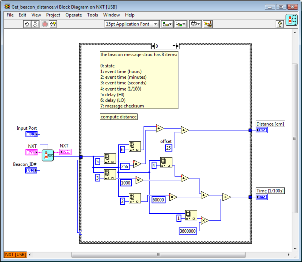
- The receiver
stores a long message at each measurement event (data-struct
see below), composed at this point of the development of non-changeable system
information and beacon data.
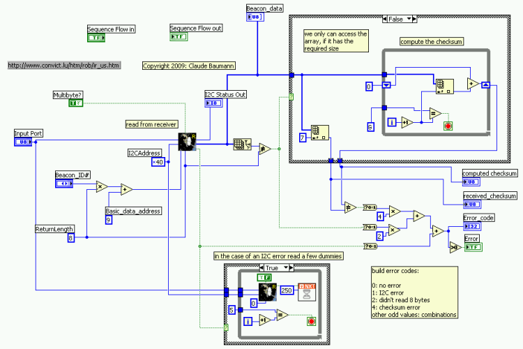
- I2C requests from
the NXT force the device to return the beacon-data to the NXT-module.
Device address is 0x40. The device sends multi-bytes, among which a valid-data-state
value, indicating, whether the current data is (or is not) being changed
by a new measurement. Further the current device-time of the measurement
and the distance in cm (two bytes big endian). The beacon-data packet is
completed by a checksum.
 In
the actual firmware only the beacon data is available In
the actual firmware only the beacon data is available
|
|
3. NXTs
- the NXT equipped
robots should know the positions of the various beacons
- for slow motion
robots the current position can be deduced by trilateralization
- fast moving robots
need additional dead-reckoning methods fed into a Kalman filter in order
to find a best estimate of the position.
- NXTs must provide
the 4.3V AND the 9V power-supply for the receiver-device. The data is
asynchronously retrieved through I2C.
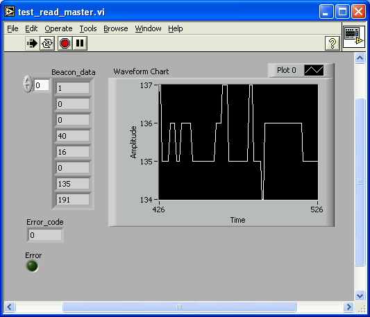
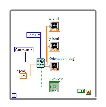
Here a simple ROBOLAB 2.9.4 program that fetches
the beacon_ID#0 data from the receiver and
displays the results:
Thanks Chris Rogers for the
hints. (I2C sub.vis may be found in ..\ROBOLAB29\vi.lib\Swan\Swan.llb)
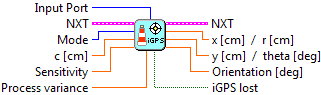
With the LabVIEW toolkit, we get the
following results:
Note that, at this
point of the development, the time stamp only indicates the time since the start
of the receiver.
4. Test-results:
The first tests with the device show the
following results:
Notes :
-
For test
reasons, the 16bit timer value that determines the measured distance in
maximal 65535 steps of 0.3mm is converted into cm, with an obvious loss of
information.
-
These first
tests do not distinguish constant errors that are due to the constant offset
of the ultrasonic detector, from spurious errors.
-
Future firmware
will return the raw 16bit timer value that the NXT can convert into distance
through x=c*t.In order to get even more precision, the user could add a
temperature sensor that might help fixing the thermo-variable sound
velocity.
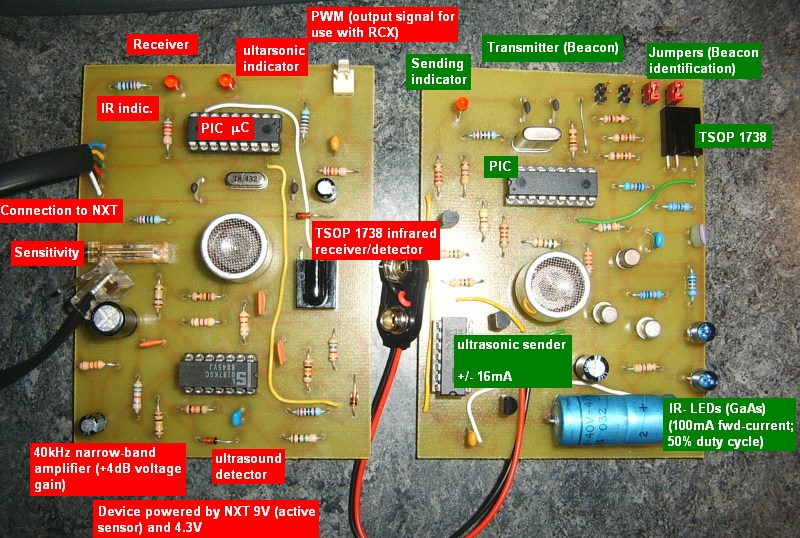
5. Schematics
Characteristics:
-
beacon jumpers : XXX Y,
where XXX = ID# number (or, in the case of the master beacon number of
slaves N_s); Y = Master (set); Slave (cleared)
-
beacon IR-sender: transistors
T1/T2 work as a digital AND-function. If the TX line goes LOW, T2 is
conducting and the carrier signal
switches T3 via T1 powering the IR-LEDs. The circuit assures 100mA fwd current
through the LEDs, producing a very high infrared light intensity. The
carrier-signal is generated through the PIC16F628 PWM module.
-
beacon ultrasonic sender: the
2x3 IC3 4069N drivers allow sufficiently strong currents through the ultrasonic
transducer that oscillate between -16mA
and +16mA , thus generating a high
ultrasonic signal strength. The oscillation at 40kHz is generated through
alternating HIGH/LOW states of PIC16F628 RA1/RA2.
-
The receiver ultrasonic
amplifier has high gain, with a significant maximum at 40kHz. The following
signal detector has reaction speed less than 40 microseconds. This delay
produces an offset that should be taken into account in the evaluation of
the distance measurement.
-
The sensitivity of the
comparator should be regulated to produce best reaction in the presence of
40kHz ultrasonic signals. Since the sensitivity voltage is proportional to
the battery voltage that directly powers the amplifier, the comparator
will react similarly at any battery level. (Regulation of the sensitivity
should be done with the volt-meter applied to the output of the
comparator.
-
Note : The receiver PWM output does
not work in the present firmware.
Last minute changes:
-
Laurent Kneip
suggests that beacon transistor T3 should be added a 200Ohm resistor
between collector of T2 and base of T3, in order to
prevent too high BE-current.
In the
realized beacon circuit, PIC16F628 pin RB3 produces the 38kHz infrared
carrier instead of RB0 (not changed on the schematics
yet.) In
the realized receiver firmware, the IR and ultrasonic red LEDs have been
exchanged inadvertedly (correct on the PCboard-photo
below) added on 2008/03/18 : when
sending IR-signals, there is a voltage drop that is sufficient to trigger
the infared receiver on the beacon circuitry. We therefore added a 100nF
capacitor directly soldered between the power-supply pins of the TSOP1738.
(neither indicated on the schematics nor visisble on the photo.) the schematics indicates
TSOP1740, which is wrong.
6. PC-boards
7. PIC
firmware
The firmware has been realized
with ULTIMATE for PICs.
|
|
2009/01/24
8. addons
-
We
got our copy of Michael Gasperi's book "LabVIEW for LEGO Mindstorms NXT".
Great job Mike! So, it was time to start playing with the toolkit again.
-
Since
this project was still on the workbench, it seemed to be the very first to
get the input from the book.
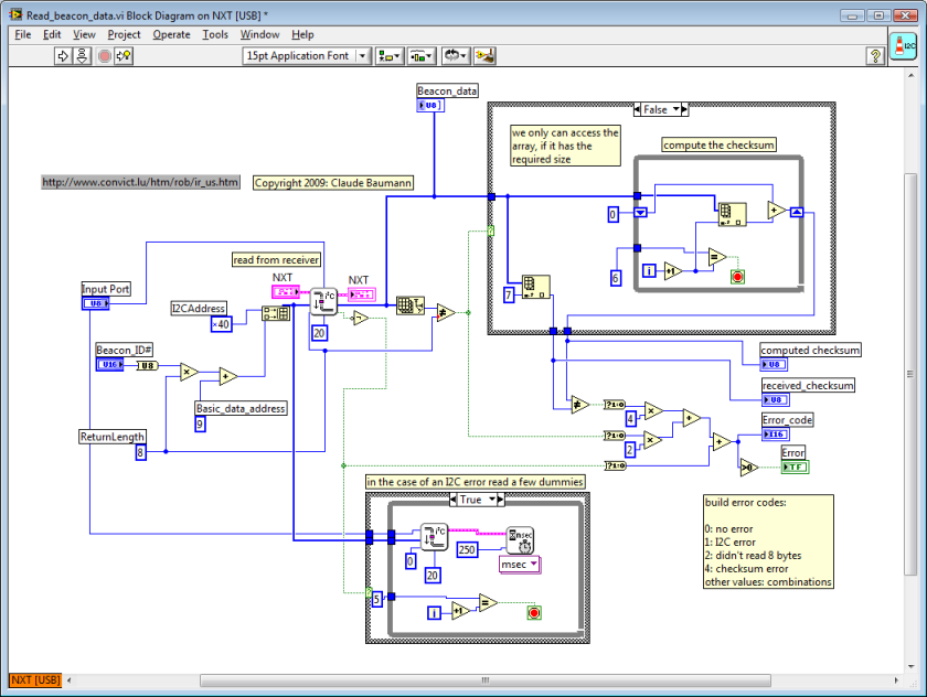
Updates
from the former version (cf. point 3 above):
-
Download LV7.1
NXT toolkit code
-
Much
simpler code; consequent use of the sequence wire; creation of sub.vis
-
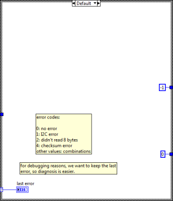
We
added error messages for the three main error states:
For
some reason the PIC firmware does not add the very first "1"
(denoted "valid") to the data-checksum computation. This probably
caused some headache to those who tried to rebuild the system. Sorry for
that. In the NXT toolkit program, the first array-field therefore isn't
counted either (which also was done above, but we forgot to mention it!!) -
There
is a nasty bug that needed a long time to be fixed: in earlier tries, if an
error occurred, the program just stopped with the mention on the NXT
display: "file error". The reason for it was that through the
program we are using dynamic data-arrays that may have zero size in the case
of an error. If then we attempt to read at any index, the NXT traps in a
fatal error state and stops the program. There is no warning or error
message in LabVIEW for this event, neither during design-time nor debugging
time. (NI guys, consider adding that error message on the PC-screen!!!) We
are pretty sure that non-experienced users will seek during extremely long
time and desperate here. Mike, could you add a note on your web-site as a
complementary instruction to your book?

|
|
2009/03/25
9.
1D-navigation with a scalar
Kalman filter
The
infrared-ultrasonic beacon-system represents a real global positioning system.
Navigating a robot with such a system is as difficult as using a real GPS. The
main issue that we already dealt with while developing our soccer projects
-where we used the LEGO camera as global positioning system- is that we receive
the GPS-data with a certain delay and at uncertain moments. Normal averaging
methods can retrace the robot path, but cannot control it, because they don't
tell us the actual position. Here now for the very first time, we are using a
scalar Kalman filter for driving a robot on a straight line, where we want the
robot to follow a 1D-trajectory. This means that the robot should meet certain
target-points at precise moments.
The
beacon system uses the Master-beacon alone with the receiver. But we configure
the Master so that it thinks there was another Slave beacon. By this way, we
only send a new update every second. By comparing the received time stamps and
verifying GPS-errors (let's denote the system as such), the NXT deduces whether
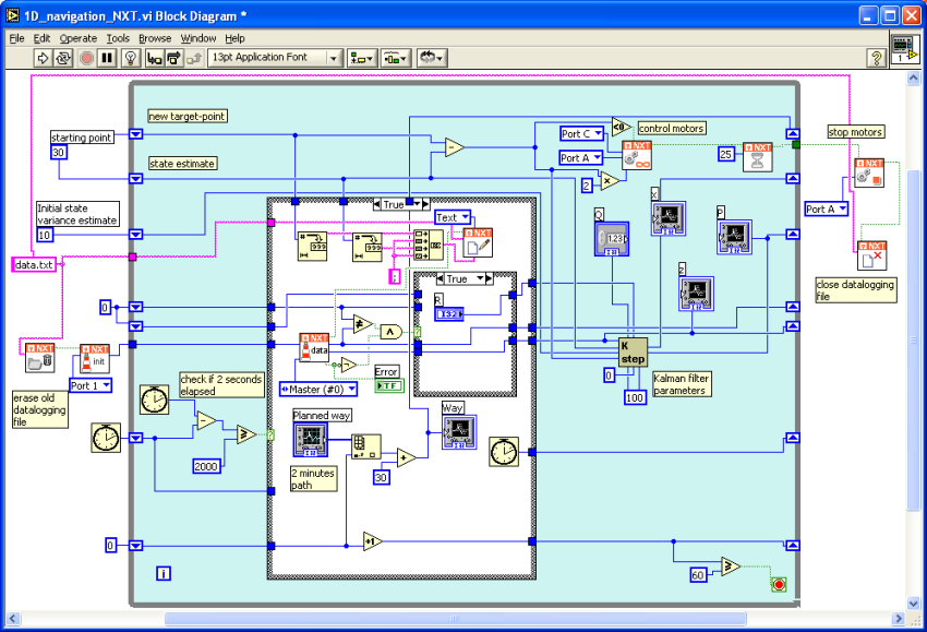
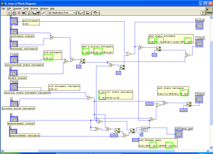
there is a valid update. The data is fed into a scalar Kalman filter that we
wrote entirely in the LabVIEW toolkit -no matrices were necessary-. The Kalman
filter essentially predicts the robot's position from the sensor data and its
internal model of the motion-system. It then compares the prediction with the
new sensor-values and adjust the statistics of the positioning-processes and
readings. Finally the prediction is corrected to form the very best estimate of
the robot's position along the straight line.
The
motors are controlled from the differences that are noticed between the
different target-points and the estimated positions.
The
program logs the data into a text file from which we extract the results. DOWNLOAD
PROGRAM.
-
Notes:
-
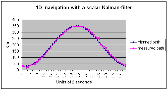
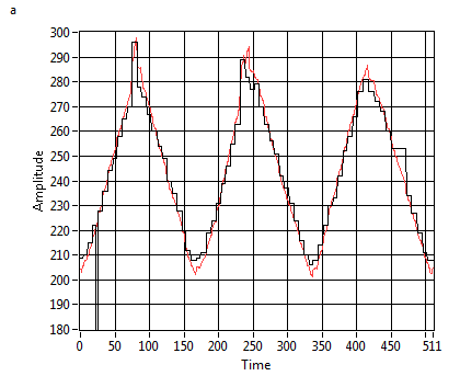
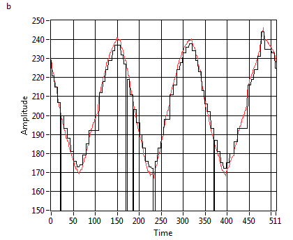
As usual for any Kalman
filter, the very first values may diverge from the real values, but
they rapidly converge, as can be seen on the picture.
-
In this particular case,
since the filter must obey a planned path, the measured path must follow
with a short delay
-
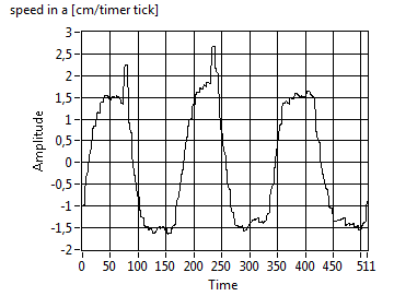
Depending on the filter
parameters, the Kalman filter has a more or less rapid response to
changes or even errors in the measurement. An error occurred at unit 45
causing the filter to react strongly by increasing the robot's speed.
|
|
2009/04/18
10. The PIC
firmware details
As
explained above, the system combines a set of beacons with a NXT compatible
receiver. The devices are driven by PIC 16F628 and 16F88 respectively. We have
been asked, if we could publish the source code. As it is written in Ultimate
for PICs, it represents a graphical code that may be easily understood as a kind
of flow-chart programs.
Links:
For
better comprehension we add the beacons' state machines hereby.
-
Note
that the infrared receiving for the beacons and the receiver works in
interrupt mode. This means that as soon as a new serial byte is received,
the ISR (interrupt service routine) immediately checks, whether the byte is
valid, e.a. that it corresponds to the expected byte. Since the IR channel
uses the very robust standard LEGO RCX protocol, each message has a fixed
header 0x 55 FF 00, followed by the fixed message code and its complement 0x
F7 08. Only then follows the message byte and its complement and the packet
checksum plus complement. If at any time the expected byte is missing, the
infrared RX channel is reset.
-
The
infrared channel is configured 2400 odd 1. Note that the RX channel does not
verify the parity, although the 9th bit is configured. (The parity bit only
has been added to complete the LEGO RCX message, if ever it was desired to
verify the message sending by the beacons easily without other additional
hardware than the standard RCX. (Interesting link about the RCX serial
configuration: http://www.robotika.sk/mains.php?page=/projects/rcxbt/
)
-
The
beacons also need the serial TX channel, which is used in back-to-back mode.
After the first filling of the TX-output buffer, the TX interrupt is
activated. At each interrupt, the buffer is refilled with the next byte,
until all have passed. When the first byte is send, the 38kHz infrared
carrier is activated (in PWM mode). The carrier only is stopped -and the
serial TX interrupt, after two dummy bytes have been filled in the TX,
because the otherwise the last two bytes in the PIC hardware buffer would
not be covered by the carrier signal. This causes a delay of 2x9x417us=7.5ms
(2 bytes, 9 bits, 1/2400 duration per bit) before the ultrasonic burst is
sent.
-
==>
Therefore the receiver will be not be able to measure distances to any
beacon below 7.5E-3*343=25.5cm !!! (speed of sound c=343m/sec)
-
The
receiver I2C channel is configured in "Slave" mode. The NXT should
provide the Master pulse. Since we learned that the bit-banged NXT I2C
master sometimes gets lost in waiting for a certain ACK that might never
come, we decided to verify every 1/100th second, if the state of the I2C
channel is hooked somewhere. If it is longer than 5 seconds in the same
state, the whole communication modules (also the UART) are reconfigured.
This important measure helped reducing the errors to almost zero, even with
multi-byte messages.
-
Some
minor features still are not implemented.
|
|
2009/10/22
11. Localizing a NXT robot in 2D with the iGPS
This
took quite a long time for the journal to awake. But, here we are again.
NEW:
-
We
finally builded a second beacon, etched the PC-board, soldered the parts,
plugged the battery... and without any trouble it immediately worked.
-
The
beacon wait-time has been reduced to 250ms instead of 1sec.
-
==>
Now we will be able to navigate in the plane with our robot
-
We
rename the whole system iGPS (= indoor Global Positioning System)
-
Recall
that two beacons are sufficient to navigate in a determined half-plane
(the beacon line must then be one of the main axis.)
-
iGPS
allows multirobot application, because receivers don't intervene in
sending infrared or ultrasonic bursts
-
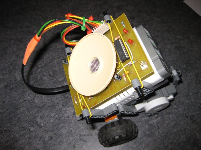
If
the beacons are placed almost in the same plane than the receiver, we
recommend adding a reflector to the ultrasonic receiver. (Unfortunately
the IR-receiver is shadowed, but this doesn't matter, because the
IR-pulses are so striong. We used the LEGO part that LDraw denotes
"Dish 8x8 Inverted" (see next picture) and drilled a hole in
the middle.
-
The
NXT now is programmed with LabVIEW Education Edition (LVEE)
We are able to localize the robot in
the plane by applying the cosinus theorem. Note that in the very first test, we
deliberately ignore that the beacons height.
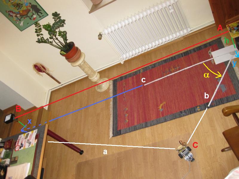
We manually measure 54°.
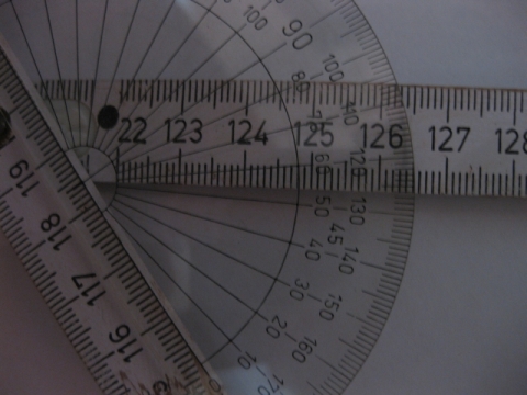
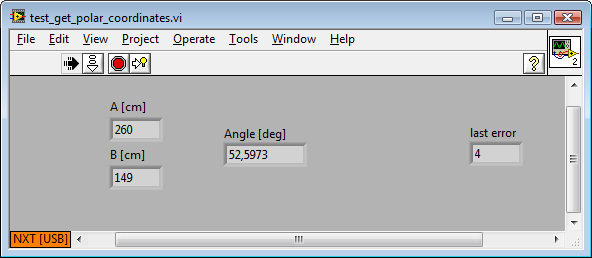
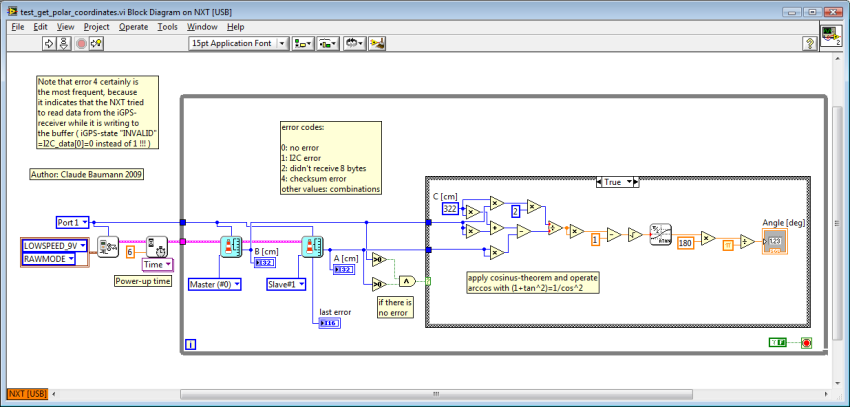
And the NXT yields the robot polar
coordinates C(52.6°, 149cm):
Here all the LVEE codes:
|
|
2009/10/23
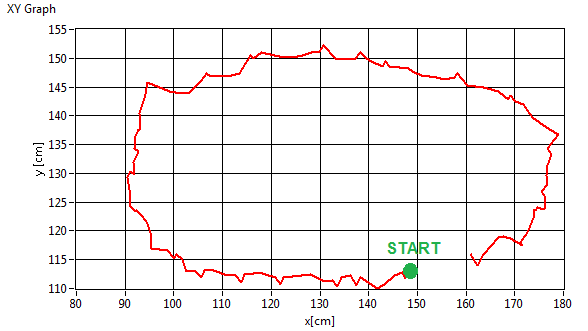
11. Follow
a black line and localize the robot with the iGPS
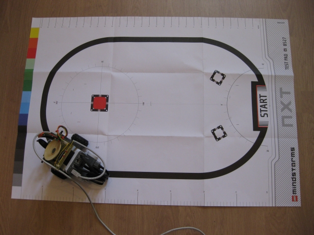
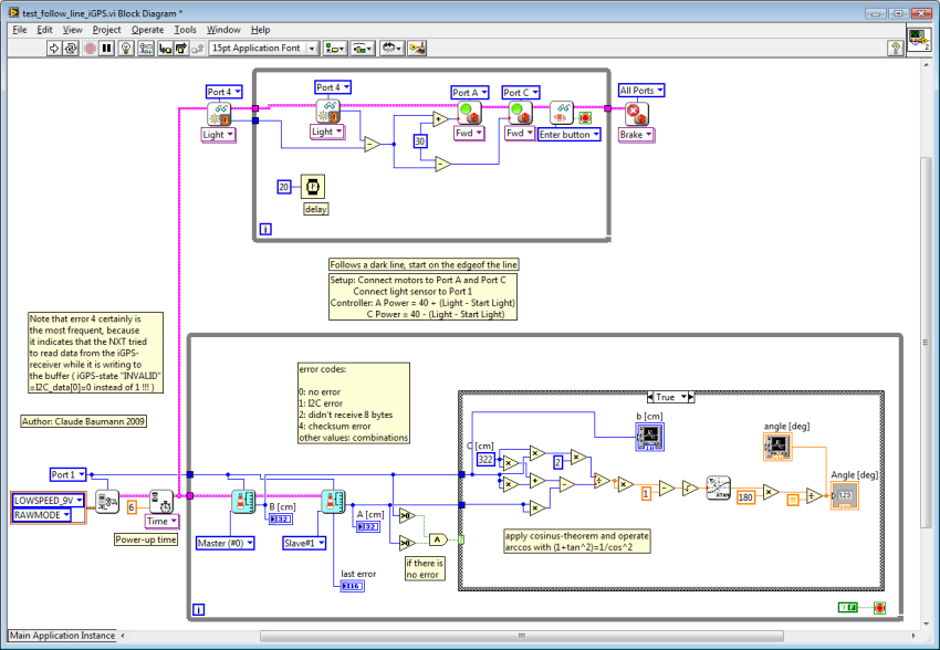
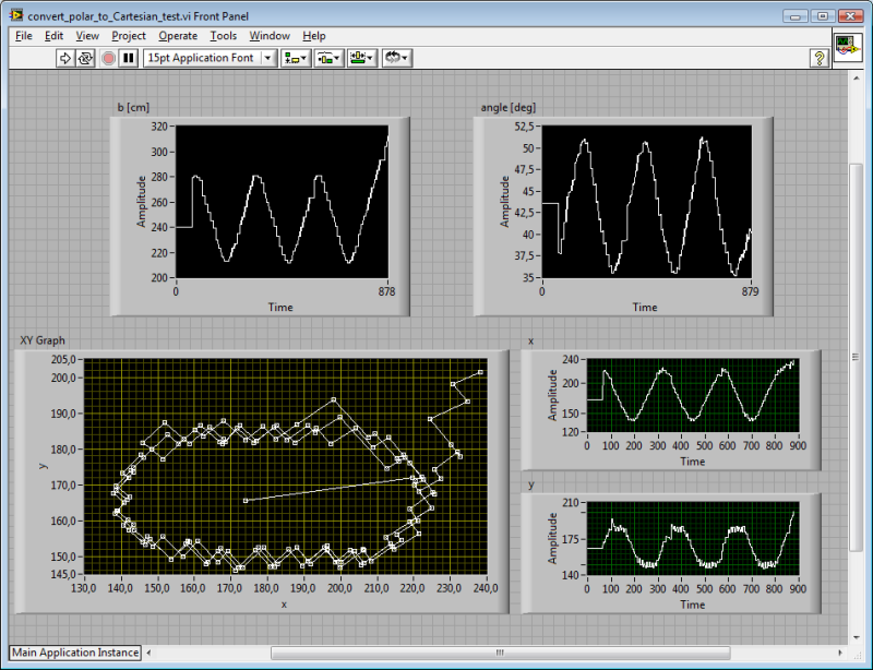
In order to test the reliability of
the 2D-localization with the iGPS, we programmed the robot to follow a black
line and upload the localization data to the PC. The program was run in
debugging mode with the USB-connection. Then we "manually" dragged and
dropped the data into a new VI, converted the polar coordinates to Cartesian
coordinates and plotted the computed positions.
Notes:
-
Inadvertently we exchanged the
master and the slave beacon, so the resulting graph is mirrored
-
The program uses the LVEE
line-follow behaviour
-
The constant c=322cm was not
measured, but just estimated. Its inaccuracy and the fact that we still
ignore the height of the beacon locations explain the distortion of the
curve.
-
The robot uses the light sensor
in order to detect the black line. The algorithm does not produce the usual
bang-bang line following, but a very smooth reaction.
-
The last turn, the robot lost the
line and went off the oval.
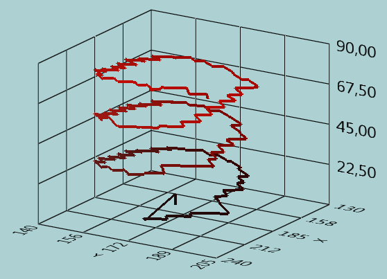
-
We draw a 3D-graph in order to
show how the three turns that the robot takes overlay.
-
The zig-zag in the line come
from the fact that the actual position is only deduced from iGPS data that
is off phase by 250ms.
|
|
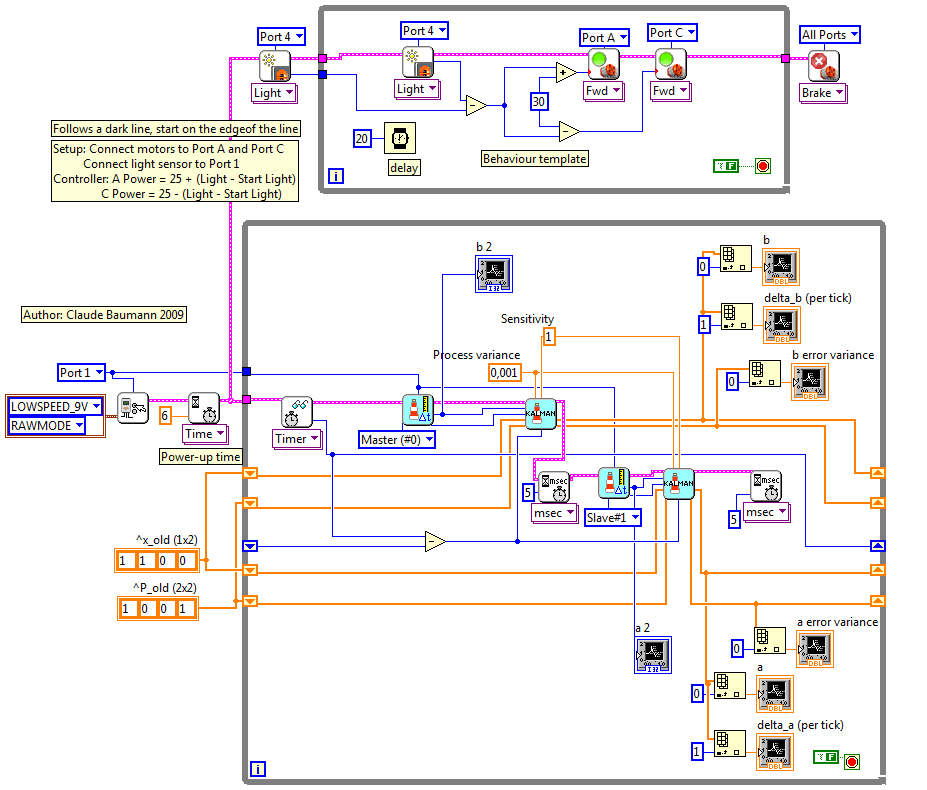
2009/10/27
12. Follow
a black line, localize the robot with the iGPS, while processing the data with a 1st
order Kalman filter
By now we have presented the scalar Kalman
filter on this site. But, in order to efficiently navigate a robot with our iGPS
system, we must this time implement a first order Kalman filter. This implies
that we need to build a matrix-based filter that is able to describe the process
as a state-space model with a state variable that is composed of a process
variable and its derivate.
There are not many people who have played with
the Kalman filter on LEGO bricks. Here a list of the most important available
online work:
As usual we wanted to write the Kalman filter
code in LabVIEW Educational Edition. There is one important limit to the
implementation: the LabVIEW toolkit does not support 2D arrays. The solution to
this issue is to reshape the 2D matrices into 1D-vectors and pick all the data
from there. That's exactly, what we did. There are some important limitations:
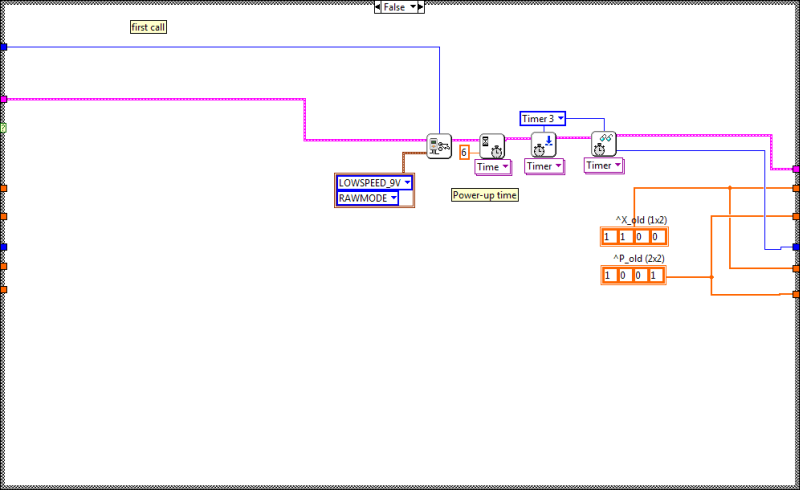
- The Kalman filter step function is limited to first order state space models and thus uses 2x2 matrices.
- Since the LV NXT-compiler does not support 2D arrays, all 2x2
matrices are reshaped to 1x4 vectors, where the order is: a11, a12, a21, a22
(The first index indicates the row, the second one indicates the column)
- The state variable is a 1x2 vector, because a first order state space model has only depth 2. (However, due to a compiler
bug, the vector must be filled with zeros to 1x4.)
- The measurement vector is 1x1 or 1x2. (Fill up with zeros to 1x4)
The control vector is 1x1 or 1x2. (Also fill up with zeros to 1x4)
- R must be 2x2.
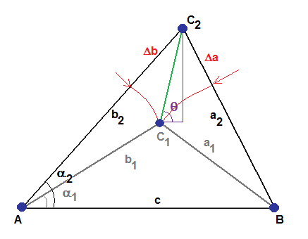
Now let's try to model the robot. First, we
consider the black line as the planned path. We don't need to tell the robot
more about the path, as we did in the 1D-experiment.
Instead the line following algorithm and the black line are responsible for this
task. To keep all linearity, we localize the robot in triangular coordinates, as
explained above. Once localized, with no effort we can turn these coordinates
either in polar or Cartesian coordinates. Because the triangular coordinates
represent distances to beacons, let's denote the main variable
r
that represents the radius of
the circle with center beacon M
. (Practically, in our case, r
either equals a or b and
M
is beacon A or B.) We have the equation:
which expresses the fact that the next position
is defined from the old one and its derivate (the speed). As a discrete time system, we
assume that  and we prefer the index k to the time index t:
We define the state as:
Recall the rules of matrix calculation. (A review
is really indicated, before continuing)
This equation suggests that the derivate does not
change over time, which in reality is not true. Yet for the moment we will
ignore that the process suffers from disturbances and is not submitted to
control.
For now we only rely on one single measurement
z(k)
hat is related to the state variable through the equation:
and where
v(k) is the measurement noise. Note that the product of
a horizontal vector with a vertical vector is a scalar and the noise
v(k) has the same dimension.
Thus,
z(k)
is a scalar (with matrix dimension 0). Notice that, when defining the parameters
for a Kalman filter, it is always essential to follow the dimensions of the
various matrices. The following schematics of the Kalman filter procedure has
been copied so often on the web -without reference- that we reproduce it here
with all the credits to the authors ( http://www.cs.unc.edu/~welch/media/pdf/kalman_intro.pdf
). Note that it was picked from THE Kalman filter reference site: http://www.cs.unc.edu/~welch/kalman/index.html
:
Q describes the process covariance.
In the present example, the robot movement is part of the process noise, because
in the equation above, we didn't add any control variable. In fact, B
and u(k) are always zero in our example. Q and P
have the dimension 2x2. We assume that the noise of the position and the speed
are not correlated (which is obviously wrong, because any disturbance in the
speed also changes the position and vice-versa.). Therefore the non-diagonal
matrix elements are set to zero. Why such an assumption then? Q is one of the
most important parameters of the Kalman filter. As Q gets smaller
compared to the measurement variance R, the Kalman filter believes
more the model than the measurement. Anyway, during the process, the error
covariance, which is a fusion of the process covariance and the measurement
variance, will show that the errors in position and in speed are correlated.
The dimension of the Kalman factor K
must be 1x2, because in the Update equation (2) it multiplies with the
scalar
z(k) .
Remember that a few lines ago we underlined that
z(k)
had dimension 0. We also have seen that the product H.x(k) is a
scalar.
 also represents a scalar that you may easily verify
through the following example:
also represents a scalar that you may easily verify
through the following example:
Hence, R must be a scalar. However,
the current LabVIEW sub.vi does not verify the dimensions of the matrices. On
the contrary, it is programmed to always operate the 2x2 inverse matrix.
Therefore it is essential to design R as a 2x2 diagonal matrix
with a dummy 1 in the right corner. Otherwise, the inverse matrix function will
return an error value.
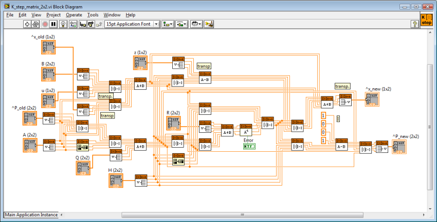
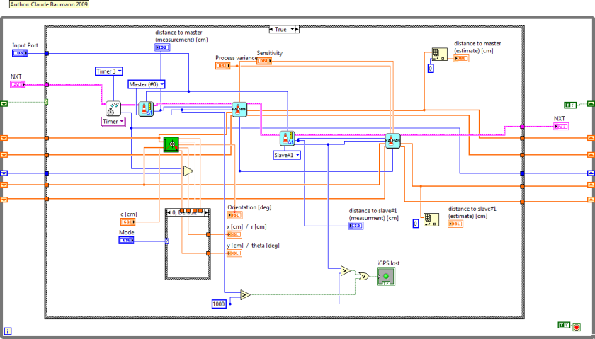
Here the first order Kalman filter step function.
It looks impressively complex, but its execution only takes 15ms on the LEGO
NXT, which must be considered as excellent timing.
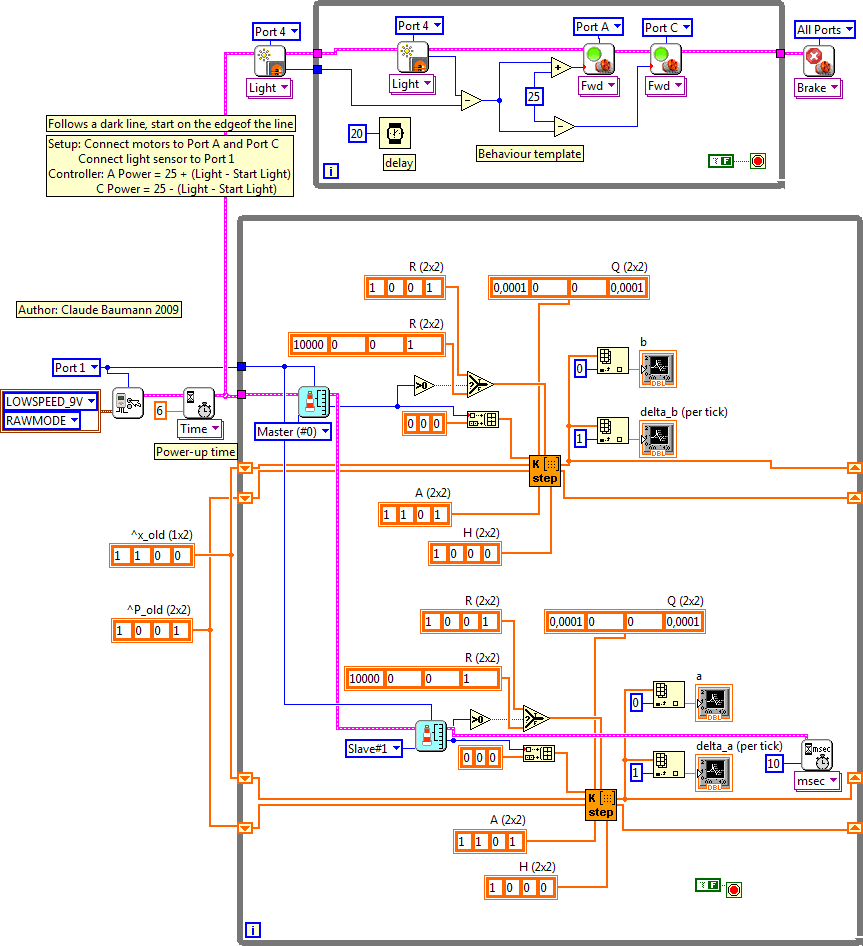
And the iGPS navigation program changes to the
following diagram. Notice that we increase the variance R, if the
iGPS data is invalid. The high variance tells the filter to ignore the last
measurement. The reaction of the filter is very impressive. We could improve it,
if we dynamically increased the sensor variance, as the duration from the last
valid measurement increases.
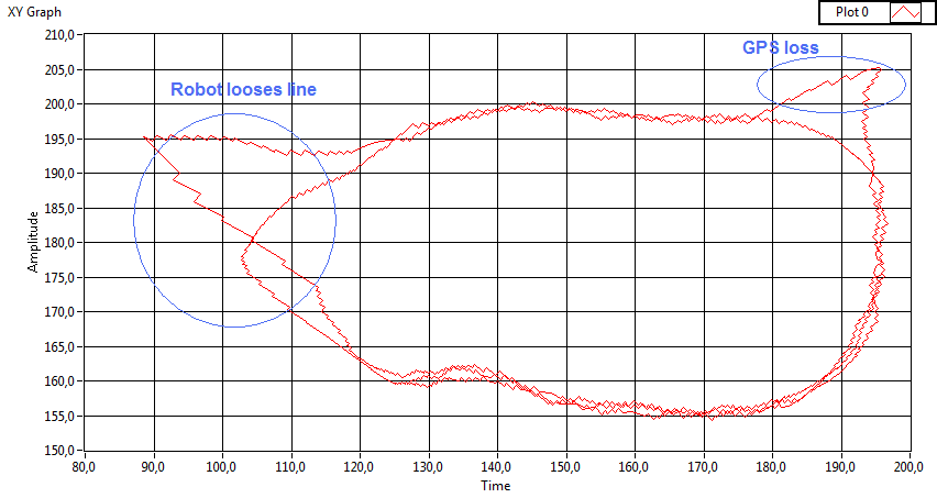
It is astonishing that the two events, on one
hand the robot loosing the line, on the other loosing the iGPS signal, do
generate the same kind of error in localization. The difference in reality was
that during absence of the iGPS signal, the robot continued moving correctly on
the line, whereas the second time, the robot completely went off the line and
had to be replaced manually. Without any other knowledge, from the data alone,
we cannot distinguish both cases. But, the loss of the iGPS signal can be
compensated, if we add a second sensor to the system. We try to improve the data by
dynamically adapting the measurement variance in function of the elapsed time
since the last correct reading of a beacon value.
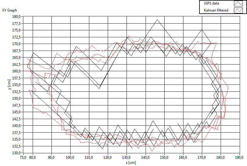
The following xy-plot is the result of a very
small process variance Q=0.0001. Remember that this value,
compared to R=1 indicates that the Kalman filter should believe
more -but not explusively- the model prediction than the sensor reading.
|
|
2009/10/28
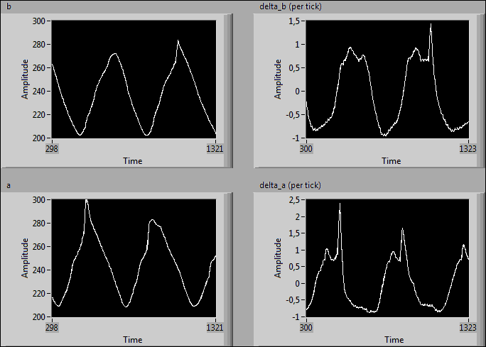
We now use another iGPS sub.vi that returns the
distance to the beacon and, for each beacon, the elapsed time in milliseconds
since the last valid data. Obviously, if we have a valid measurement at a
certain moment, we will have to wait 500ms, until the beacon sends again. During
that time, the robot will displace by about 3cm and the sensor value that enters
the Kalman filter has worse variance. Therefore, the iGPS Kalman filter function
computes the travelled distance since the last beacon update and increases the
measurement variance R accordingly. Now, the filter error variance
is no longer fixed to the convergence value, but changes over time.
In the next example, the resulting graph is less
smooth, because we tolerated a higher process variance. Note the additional
variable "Sensitivity", that is a scale factor for the influence of the elapsed time since the
last valid data.
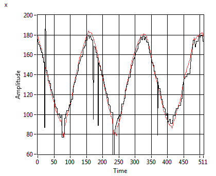 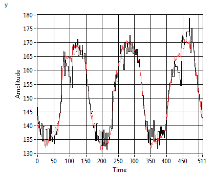
Tuning the filter is not too complicated. As a
rule of thumb, we should compare (overlay) the measurement and the estimation,
and adjust Process Variance and Sensitivity in order
to get a smooth curve. We added a scale factor "h" to
the iGPS_Kalman filter VI that helps squeezing the resulting curves. (Note that,
if the filter is too strong, it looses actuality (phase-shifting) and also
stretches the curves. So, for post data processing, a stronger filter might be
preferred, but in a life application, actuality is more important.)
|
|
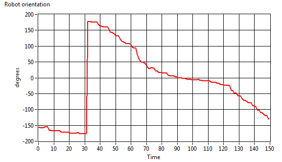
2008/10/29
The information that the iGPS system has gathered
with the Kalman filter is sufficient to also yield the orientation of the robot.
The main idea is to use the latest estimation of the beacon distances and the displacements in the
triangular coordinate system and convert them to cartesian coordinates, while
deducing the orientation. Anyway, since there is no other measurement of the
orientation that might correct the prediction, we can assume that this
estimation will be the best that we can do. Thus, this ahead fixing of the robot
orientation will depend on the overall error of the filtered data. However,
because the transformation into Cartesian coordinates is no longer linear, the
error will not propagate in a linear way either. The easiest way to estimate the
errors that propagate through the non-linear system is applying the Gaussian
method. Here a few references that introduce this method:
If the variance of the orientation is needed, the
program should include the calculation of two discrete derivates and apply the
error propagation formula for variances.
Another idea is to operate a Taylor linearization
of the non-linear functions and tranform the Kalman filter into an Extended
Kalman Filter (EKF). (This is not indicated here, since the actual matrix Kalman
filter is only implemented for 2x2 matrices.)
Another test gives us the orientation during a
robot run over the circuit:
|
|
2009/10/30
13. Convert the
triangular coordinates into Cartesian coordinates
Now the program should convert the triangular
coordinates from the iGPS trilateration into Cartesian or polar coordinates. As
we already pointed out, this conversion-functions are no longer linear. For our
present project however, this does not matter, because with the excellent
precision of the iGPS distance data, error variances can be assumed very small.
But, we will test this. The LabVIEW program that is run in debugging mode
appears very smart:
For it was possible to run the device with
approximate beacon positions. Also we corrected the offset by a constant (25cm
that we tried to explain above - probably we were wrong in the interpretion).
- We noticed that weak beacon 9V block-batteries
have an effect on the offset, although the receiver is stable for beacon
battery voltages down to 8,3V. Below this value, the offset grows.
- There are no differences between the master
and the slave beacon. (A study here can only be made, once we have more
beacons.)
- The NXT voltage does not affect the readings.
- We took off the plastic reflector, because we
found that the shadow on the IR-receiver was too bad and also increased the
offset.
- The offset is slightly dependent on the
distance. So, we add a correction function to the main distance extractor
VI. (d=1.0191*x+4.2133).
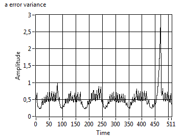
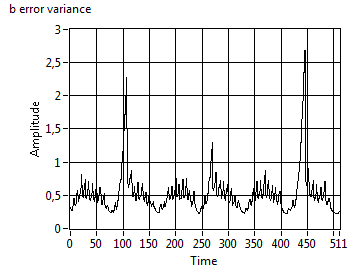
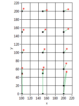
The very first tests yields the following graph
- Note that the results are based on the Kalman
filter data and that the filter has not been fine tuned yet. from the graphs
above, you can see that the filter slightly overestimates the true values
- The standard deviation never exceeds 1 [cm]
both in x and y.
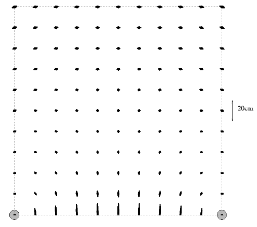
- The graph is very similar to the thoroughful
study of the Höhrmann's
project, from which we pick the error-graph of a simulation with a
two-beacon scenario.
- Beacon spacing was 325cm
- Errors are largest between the beacons
Conclusions: The results can be improved, if the
Kalman filter is tuned. This however may take quite a long time.
|
|
2009/10/30
14. Some more tests
- long range test without reflector:
- beacon and receiver aligned: maximal
measurable distance 16.40m
- beacon at 2m height, receiver horizontal:
maximal distance 5.70m ==> might be an idea to rethink about using a
reflector; but the plastic reflector above hides the IR-receiver!!!
- The team will build 2 more beacons. So, there
will be 4 and complete 3D-positioning will be possible.
|