(You may write as well an according nqc-program.)
3. Making the device operational
(Testing and calibrating)
Follow the instructions step by step!
Build the turnable beacon according to the instructions at the turnable beacon page. [If you want a more reliable base, choose the altered support (look at the date 17/7/01)]. Connect the wires as shown! The RCX will be called RCX_A.
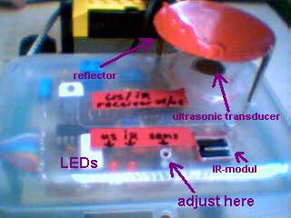
Connect the power-line of the IR/ultrasonic receiver to the output B of a second RCX (so called RCX_R).
Connect the output-lines of the IR/ultrasonic receiver to the input-lines of the D/A-converter.
Connect the output-line of the D/A-converter to the input 3 of RCX_R. Put attention to the polarity!
Download the following program Test_IR_US2_sender.vi to RCX_A.
(You may write as well an according nqc-program.)
Download the following program Test_IR_US2_receiver.vi to RCX_R.
Here are some pictograms which are not so common, as they belong to Robolab version 2.0 with installed extras (Investigator). The second icon corresponds to the nqc-command until(SENSOR_3>0), where 0 means 0Volts. With nqc configure the sensor-input as a passive sensor with Set SensorType(SENSOR_3,SENSOR_TYPE_TOUCH) and SetSensorMode(SENSOR_3,SENSOR_MODE_RAW). Robolab configures the sensor-input as generic, so it will return real values from 0 ... 5, whereas nqc will return values from 0 ... 1023. The fourth icon is identical to pushing the VIEW-button on the RCX-body.
Place the beacon exactly at 1m from the receiver so that it points in direction of the receiver. (extreme points: ultrasonic parts)
Start the RCX_R program. After a little pause the IR-LED will light up shortly. This shows the device is working.
Start the RCX_A program.
Adjust the potentiometer on the sender-board to optimize the pulse-frequency to 40kHz. To do this, start at the left most point, then turn very slowly to the right until the receiver's IR-LED lights up regularly. Note the angle of the potentiometer. Then continue turning until the lightening of the LED stops. Now turn the potentiometer exactly to the midth-position of the two angles. Because of the symmetry of the IR-modul's respons-curve, this point must be exactly 40kHz.
Now adjust the sensitivity of the ultrasonic receiver-part. Turn the potentiometer to the right most position. Then turn slowly to the left until the US-LED starts lightening regularly AND the RCX_R SENSOR_3 values turn around the raw-value 890 (e.a. 4.35V, if you are using the ROBOLAB-investigator direct mode). If the value does not change from 1023, turn back to the right very, very slowly. Observe the values. If the IR-LED continues lighting up alone, the ultrasonic receiver doesn't get any signal. Make sure the beacon points exactly in the receiver's direction.
The sensor-value may be transformed to cm using the following formula:
d0[cm] = 604.42637 * (1023 / RAW - 1) formula 1
Notes:
the D/A converter obeys to the formula: X = 137.67 * (1023-RAW) / RAW, where X is the delay between the IR and the ultrasonic impact. This is equivalent to X = 137.67 * (1023/RAW - 1).
the distance may be calculated as: d [cm] = X * 0.128E-3 * c, where c is the sound-velocity, which is 343E2 cm/sec and x the number of measured time-units of 0.128ms. ==> d[cm] = 4.3904 * X
Now calculate the distance. You'll note that the computed value is less than 100cm. Due to the increased sensitivity of the ultrasonic sensor, we have to consider the respons-delay of the IR-modul, which is typically to be found between 7 / f0 = 7 / 40000 = 0.175ms and 15 / f0 = 0.375ms. This corresponds to an off-set distance of 6 ... 13cm. Note the off-set value, which is 100-d0. This value has to be added every time, the RCX_R calculates a distance from the RAW value. So formula 1 has to be transformed to:
d [cm] = 604.42637 * (1023 / RAW - 1) + doffset formula 2
or
d [cm] = 4.3904 * X + Xoffset ---> (xoffset = doffset / 4.3904) formula 3
NOW THE DEVICE IS READY FOR USE !