|
JOURNAL (II
very long)
go
to journal (I)
go
to journal (III)
|
most important
links
|
2008/05/23
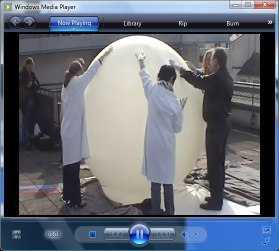
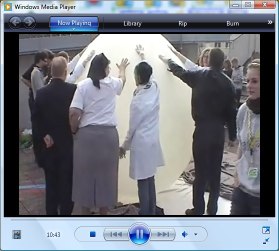
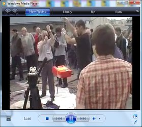
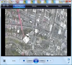
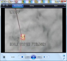
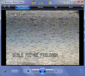
- We could follow the launch and ascension of Fieldgen
meteo balloon (please consult journal page 1) this morning over their video-stream. Some notes and
screen-shots:
- excellent PR-action
- interesting ham activity
- remarkable educational initiative. Well
done guys!
- the balloon and the payload rotated
enormously during the ascension. This surely was the main reason for the
bad picture quality. (Question: could there be added some inertial
stabilization to ours?)
- once passed 10000m, the hygrometer
returned -4% (negative relative humidity !) The sensor perhaps was
dependent either on the temperature or the pressure (200hPa), or both
- above 8000m the temperature inside of the
payload started to be negative (-2°C-decreasing at -48°C outside
temperature)
- at 12000m they measured -45°C oustide and
-9°C inside
- at 23000 the outside temperature was -38°C
and the inside value was -4°C
- when the payload descended at 12000m the
inside temperature was -18°C
|
|
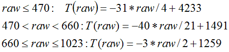
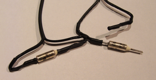
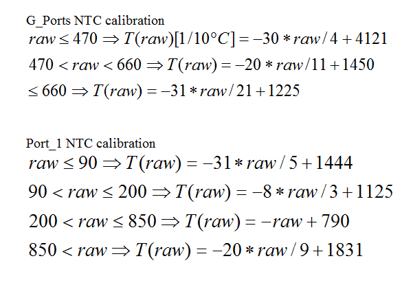
- Calibration of the new 10k NTCs connected to
Gasperi's RCX input multiplexer. Probably due to the package and the
metallic head, the LEGO temperature sensor has a slower response. The graphs
show that both sensors evolve in parallel. The difference in temperature can
be estimated to 10°C.
|
|
2008/05/24
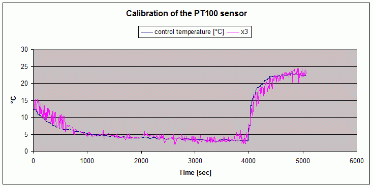
- Francis's
document about the PT100 calibration
- LUXPAK now needed a lot of work to make
everyrthing pass into the box and respect all the requirements.
Unfortunately the final design even without any silica-gel now weights
1600g. Eric's last mail tells us:
- "We now have our complete payload
set at 10480 grams:
1) David Levy (USA) 1440 grams
2) Eugene Tsai (Taiwan) 1630 grams
3) Brian Davis I (USA) 1580 grams
4) Brian Davis II (USA) 1130 grams
5) LEGO Mindstorms team (Denmark) 800 grams
6) Tufts Univ (USA) 800 grams
7) Claude Baumann (Lux) 1600 grams
8) David Martinez (Sweden) 1500 grams
As we cannot reasonably carry anymore, this will be the final list. I am
begging you all to attempt to reduce weight as much as possible. The
lighter
the mission, the higher it goes! Every gram helps!!!
I am in the process of updating the HALE website now with information on
all
the payloads and more information about building payloads.
In case you didn't see the email, David Levy has setup a Google groups
page
at: http://groups.google.com/group/hale-teams/
This is going to be an exciting experiment!!!!"
Regards,
Eric Wang
- So, we will try to find those grams that we
can save.
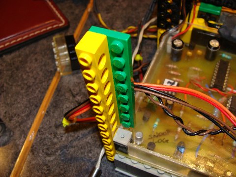
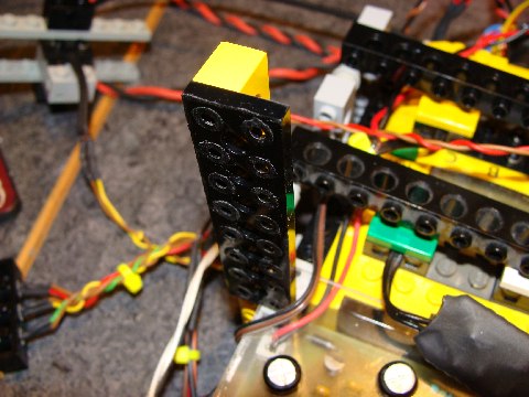
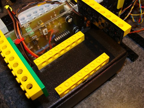
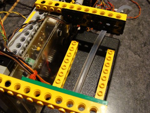
- Here a long series
of pictures of the payload assembly as decided by Francis and the
Convict-team:
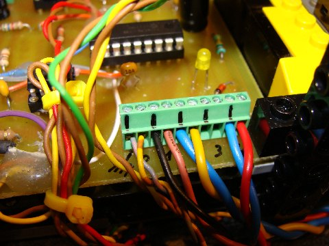
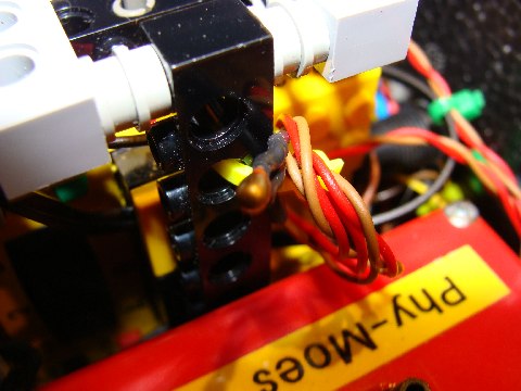
-
How the sensor wires are fixed
to SNOOP_LOG (from the left to the right: pressure sensor, ozone sensor,
PT100, light-sensor)
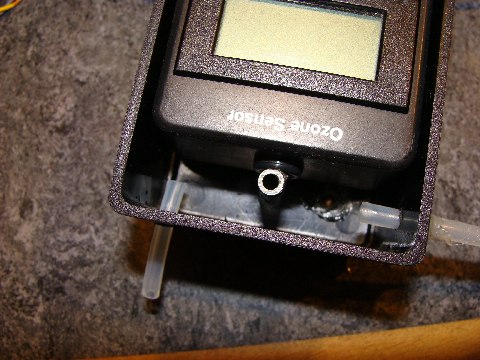
-
air inlet and outlet fixed to
the new ozone sensor box that replaces the transparent one. Note that on the
bottom of the box (not well visible) another NTC temperature sensor is
glued.
-
outlet glued to the polystyrene
box
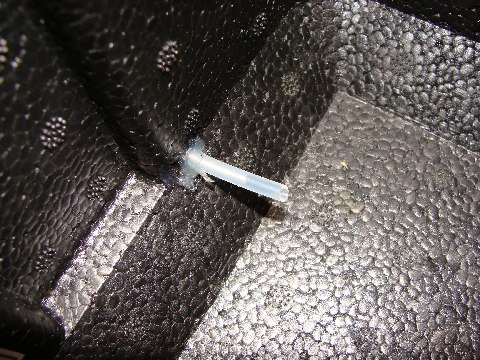
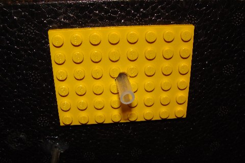
-
outlet stud outside
-
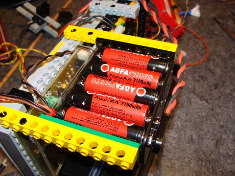
green plate helps fixing the
accus pack
-
so does black plate (studs are
cut)
-
two yellow beams are glued to
the top of the ozone-sensor box. They serve as support for the accu pack.
(Inverted disposition)
-
the tube for the balloon string
needs to pass through the middle of the payload box
-
By contrast to the group's
decision, Laurent suggests to put the accus on top in order to allow easy
access.
-
an NTC temperature sensor is
glued to Mootz_board
-
Heat-resistor wires, air-tube
and silicon isolated NTC sensor wires
-
the black box beneath the
pressure-sensor contains the Gasperi RCX input multiplexer
-
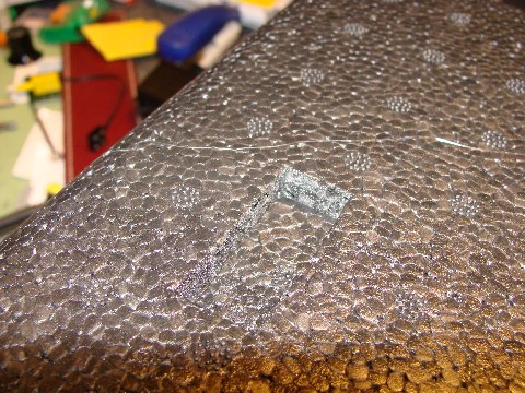
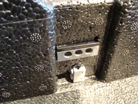
cutting the box material for the
"remove before launch" device
-
easy to cut and to press out
-
idem
-
the button and the support
pieces are glued to the box
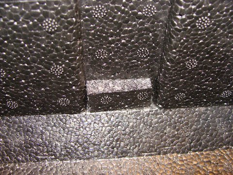 
-
a beam is used to cut the hole
for the LED support
-
inner view
-
the transparent brick is glued
to the box
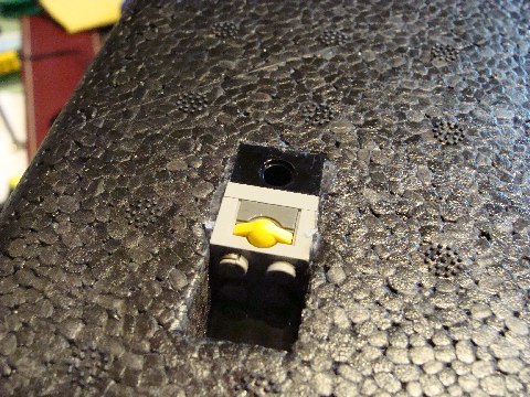
-
how the main switch is fixed
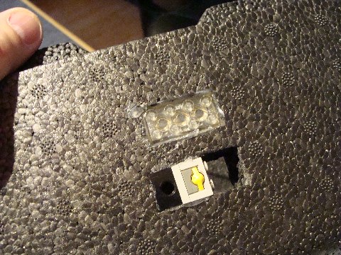 
-
the plate bridge to the main
structure will later be glued to the button (perhaps we will use a smaller
one)
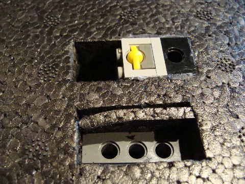
-
the PT100 cannot be fixed next
to the light-sensor (bottom) because the wires are not long enough
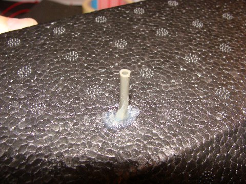
-
air-outlet stud
-
inlet-stud (ATTENTION : not to
squeeze the flexible silicon tube that makes the bridge
-
View from the side; the
silicon-protected NTC sensor has not been fixed yet.
-
Another NTC sensor that measures
the temperature in the box
-
the balloon string will pass
through this tube
-
the complete payload (the brown
paper contains the silica-gel; but for weight reasons, we cannot carry this
pack on board.)
|
|
2008/05/25
- Francis's
document on air heating modelling and experiments
==> and
the update
- Now the work consists in:
- learn about accu charging
- rewriting the RCX firmware for LUXPAK with
the new requirements:
- one heater powered from two RCX ports
- heater control :
- keep temperature in the tube at
100°C (perhaps less, as Francis suggests)
- if the temperature in the
ozone-sensor box is above 10°C (exact cut-off value has to be
determined), reduce the temperature in the tube
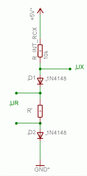
- control the sensor input port
multiplexer:
- changing the "active"
powered sensor state shortly to "passive" unpowered
state reduces the voltage from 9 to 5V and also sets high
impedance (10k). This gives an impulse to the 4017
counter/multiplexer and anothe 4066 port is activated. The
normal short sensor reading of 0.1ms is not sufficient to
trigger the counter.
- The first 4066 port to be
recognized is the one that only sends back the voltage through
the 1k resistor (raw values below 338). Now every pulse switches
the NTC sensors that are connected to the multiplexer board. The
raw values can never be below 430 as may be described in the
equations and the equivalent schematics for one
"Gasperi" port:
- if port2 values are transmitted to
SNOOP_LOG, the two most significant bits are used to determine the
active 4066 port (thus we only log temperatures on port 2 every 40
seconds). We also log the 338 reference voltage in order to detect
bad data, if ever.
- If during flight the gasperi mux
should present some mulfunction, we reduce the tube temperature to
50°C not to risk any LUXPAK overheating.
- add self-tests of the new sensors and
also the battery level, in order to detect low battery (it is a good
thing that the SNOOP_LOG heater is working right from start, because
low accu power will be seen better, if some current is drained.
- only do the SNOOP_LOG data pointer
reset on pressing the VIEW/PRGM button at the same time.
- add a conversion function for those
out of range values of the RCX ROM function concerning the
temperature sensor.
- other points?
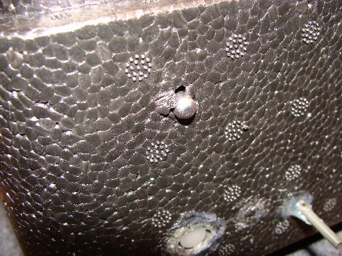
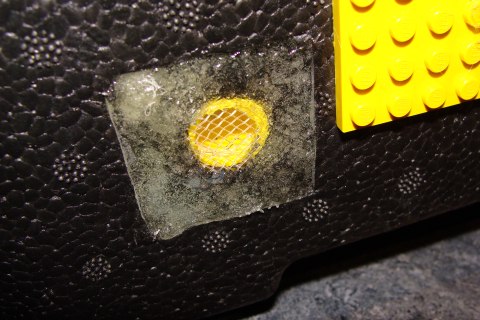
- Here a picture of the air inlet where we added
an insect filter:
|
|
2008/05/26
- Yesterday's equations model the real circuit a
bit too much. They presuppose that the diode resistance is zero, which is
not the case. Also at low voltages, the voltage-drop on the diodes doesn't
equal 0.6V, because of the non-linear response. Therefore we proceeded to
another experiment. We built up the circuit as shown above with a
potentiometer in series with a 2k2 resistor. We measured the potentiometer
resistance and noted the corresponding RCX raw value. Then we used the
indicated approximation formula to establish a calibration curve (Steinhart
& Hart):
|
|
2008/05/27
- If the NTC is used directly on an RCX-port,
e.a. not with the Gasperi mux, then the approximation function :
-
The results are very
interesting, although there still was a bug in the firmware. That's why the
regulation took so long to decrease the power, even, when 30°C was measured
at the ozone sensor.
-
The tube temperature grows
exponentially at the beginninng, then there are two moments (visible
oscillations), where the regulation reduced the motor power. The increase
at the end was due to the stopping of the air-pump. With continuous
air-transport, it will hardly be possible to reach 100°C. Thus the heat
stabilzation at 100°C can not be activated.
-
The multiplexed values are not
yet representable in a time graph. The box-sensor was heated twice over
60°C (the peaks are visible, not the real extrema, because the events
were so short.) The ozone-sensor box temperature first is reduced, as the
air-pump starts, then steadily, but weakly grows. Note that the cold N2
is heated as well. There is no noticeable drop!!! The RCX is seriously
heating under the extreme currents. The firmware should also consider this
temperature in order to protect the RCX and Mootz_board from overheating.
Note that neither the PT100, nor the light-sensor are drifting visibly.
|
|
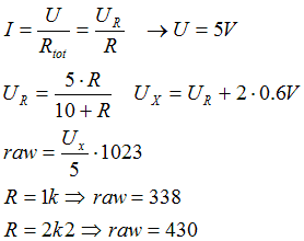
2008/05/29
-
 SNOOP_BURN PIC16F88 firmware: .asm
.hex
SNOOP_BURN PIC16F88 firmware: .asm
.hex
- Yesterday evening we proceeeded to the
"cold test":
- The RCX firmware
version 22 (.asm
.srec) was adapted with a better
temperature regulation:
- now the tube heater will be powered at
255 during the first 12 minutes of the flight in order to pre-heat
everything and overcome the thermal "inertia" of the big
resistors. The accus are supposed to be fresh and there should be no
risk what ever of overheating during this short phase.
- if the RCX voltage level drops below
8.3V, then the heater is switched off independently of any other
function in order to protect the datalogging process.
- after 2 hours the heater task is
switched off.
- if the ozone-sensor temperature is
below 20°C then the setpoint temperature (also called here
"goal temperature") is increased (maximum 80°C), else the
setpoint temperature is decreased (minimum 10°C)
- if the box temperature is below 10°C
then the setpoint is fixed to 80°C. If this temperature is more
than 50°C, there is a risk of overheating and the setpoint is fixed
to 10°C
- if the RCX temperature is below 10°C
then the setpoint is fixed to 80°C. If this temperature is more
than 45°C, there is a serious risk for the RCX to overheat and the
setpoint temperature is reduced to 10°C
- if the GASPERI multiplexer does not
work correctly, then the set-point is fixed to safe 30°C
- the firmware is programmed in order to
have a hierarchy of importance:
- lowest importance: ozone sensor
-temperature
- box temperature requirements
override the ozone sensor one
- RCX temperature requirements
override the previous ones
- first 12 minutes and overall time
(2 hours) have equal priority
- accu level has highest priority
- now the firmware sends the setpoint
value to SNOOP_LOG instead of RCX portB state, which always is
identical now to portA.
- we won't be able to use the VIEW/PRGM
button combination to reset the EEPROM data-pointer, because we want
to maintain the normal VIEW-button function.
- The test was made under worst conditions:
- weak accus
- humidity 98%
- temperature -18°C in a big freezer
- duration 40 minutes
- the LEGO compressor pumped the air that
passed through a box where we put a silica-gel pack to reduce the
humidity.
- first the quantity of air per second
was measured and calculated:
- a rotation sensor was coupled to
the pump motor (12738 pulses in 3 minutes)
- the pump motor rotates at a speed
of 12738/3/16=265.375 rot/min
- the pistons were measured: inner
cylinder: 6mm diameter, height 16.5mm ==> volume=0.4665cm3
- one motor rotation produces two
piston actions ==> air quantity/min= 257.6cm3/min
= 4cm3/sec


-
After 3 minutes the accus (that
already had served during several hours without being recharged) lost their
voltage, which first is compensated strongly by the RCX stabilization
(voltage grows to almost 10V). Then the voltage can no longer be maintained
and it drops below the cut-off value of 8.3V, where the heater is switched
off. During the next few minutes the heater switches on and off because the
battery voltage drops as the heater is on and recovers when it's off. After
12 minutes the heater setpoint is reduced to 10+C, which reduces the RCX
output power to 0. The accus now recover and LUXPAK can continue working.
After 39 minutes, the accus voltage drops below definitely switching off the
heater, because the accus are unable to recover.
-
The RCX output PWM reacts
accordingly and oscillates at first weak accus detection. The attempt to
relaunch the heater at minute 39 fails, because of the low battery state. (QUESTIONS:
does the oscillation affect the sensor readings? Could we use a smooth
decrease of the power instead of radically switching off the heater? In that
case, we would have to add a second cut-off point, where the heater
defintely is switched off.)
-
The temperature setpoint is
10°C during most of the time, because the ozone-sensor temperature is above
20°C and neither the box interior nor the RCX are in low temperature state.
However, after 38 minutes, the setpoint starts oscillating, because the
ozone-sensor temperature oscillates around the 20°C cut-off value. (QUESTIONs:
is this oscillation desirable? Especially the decrease of the setpoint seems
odd. Perhaps, we should simply allow two different setpoints (either 80°C
or 10°C)? )
-
During the second freezer
opening we moved the box a bit. Because the cover did not completely close
the box -the air-tube pass between the box and the cover-, the box-sensor
reacts drastically. The increase at the end was produced, when we took
LUXPAK out of the freezer.
|
|
2008/05/31
- SNOOP_LOG and SNOOP_BURN are in their definite
form both from the electronics and the microcontroller programs. We put
everything into one file that people can download now.
- A 710-4 LEGO wood-storage building set (1963)
from the flea market delivered a few white 1x1 bricks with printed letters
that we glued together to form a real historical and well visible
"REMOVE BEFORE LAUNCH" panel. (Eric, could you manage that we get
it back after the event?)
|
|
2008/06/02
- We measured the different currents that are
drained (all measurements at 12V power supply voltage):
- 150mA at start (with O3-sensor batteries
empty)
- after 3 minutes this current is reduced to
120mA
- the RCX firmware download needs 5 minutes,
after which the 800mW heater is switched on and the current grows to
240mA
- If the tube heater is switched on, the
current is increased to exactly 1A
- Francis determined that the pressure sensor is
linear and the calibration function can be set up easily:
0 hPa = 0.5V
1200 hPa = 2 V
thus hPa = aV+ b
0 = a*0.5 + b
1200 = a*2 + b
------------------------------------
==> hPa = 800*Volt - 400
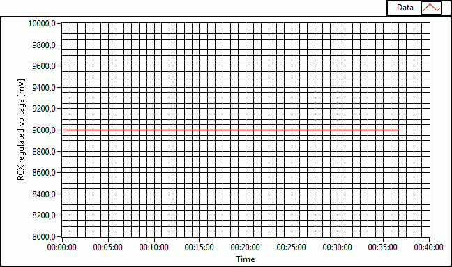
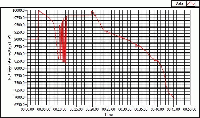
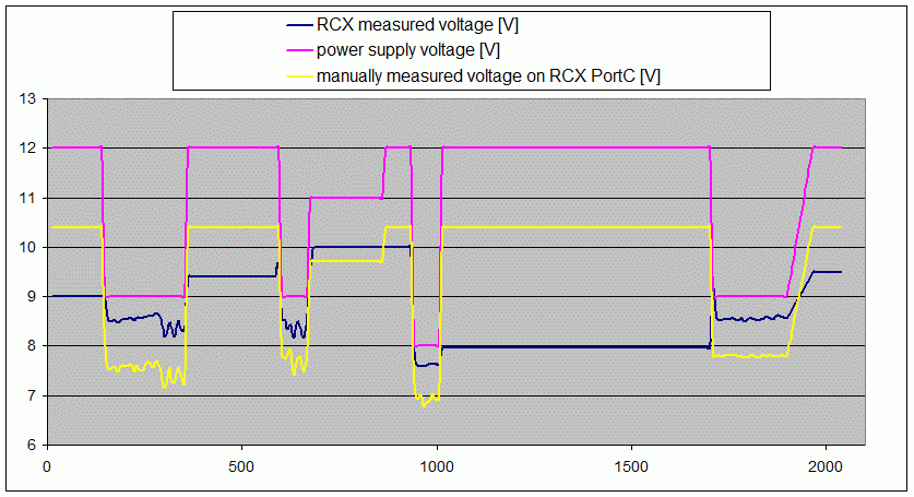
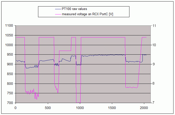
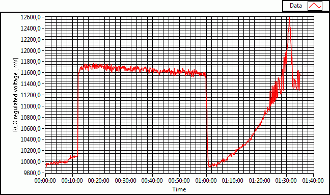
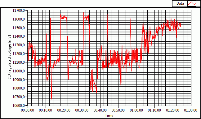
- The intriguing 2008_05_29 graph of the RCX
regulated voltage asked for deeper analysis. So, we powered LUXPAK with a
well stabilized power supply and got the following plot that in fact is the
result of the ULTIMATE ROBOLAB battery level limitation (<=9999mV). The
issue is that with values greater than 9999 the battery level is burned in
the last valid value smaller than 9999. This obviously is a bug. We will fix
it and replace this function with a new one that does not limit.
|
 |
Good news from
CONRAD Electronics:
one battery hasn't survived its second recharging. CONRAD
immediately accepted to replace it. Thanks guys! Excellent service! |
|
2008/06/03
- The new RCX firmware (version23) now respects
all the described requirements except that, if the battery voltage drops
below 8.3V, there is no smooth stop of the heater, because the battery
voltage would continue dropping and we would loose the RCX. Therefore, at
low battery, the heater is immediately switched off, which unfortunetely
leads to the undesired oscillation that we already enountered. But, it seems
that the only alternative is to switch the heater off definetely, as soon as
the low voltage is detected. This remains on the TODO-list.
- With the new RCX battery firmware module we
overcome the issues descibed above. The folllowing graph has been realized
while gradually changing the power supply. During the first 12 minutes and
between seconds 1300..2200, the heater was on. (From sec 720 to the end of
the experiment the power supply voltage was kept constant.)
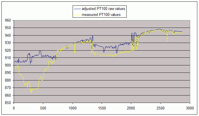
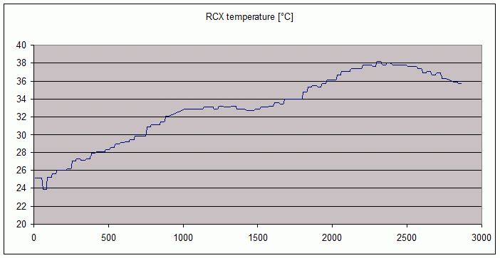
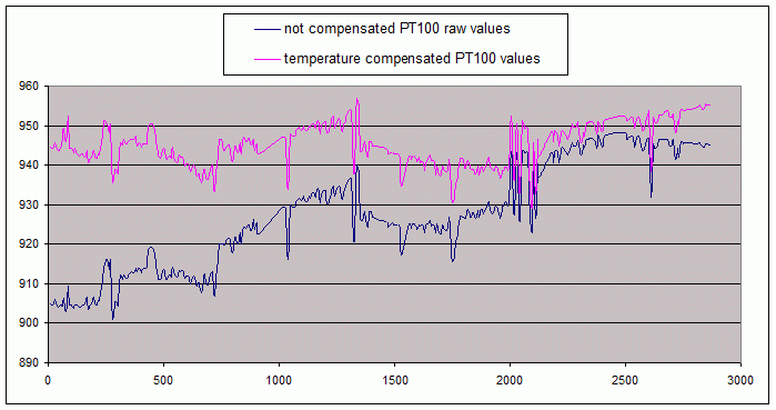
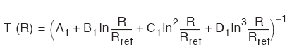
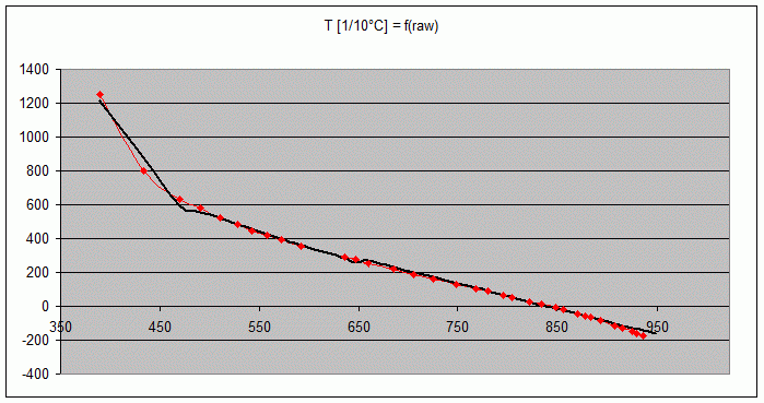
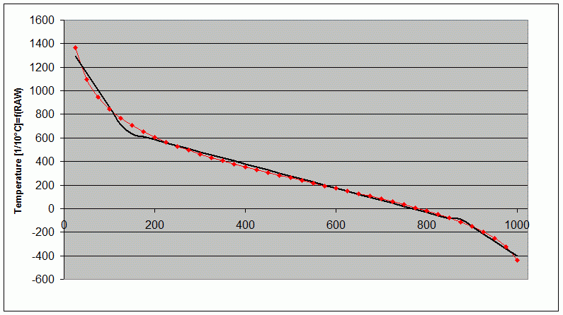
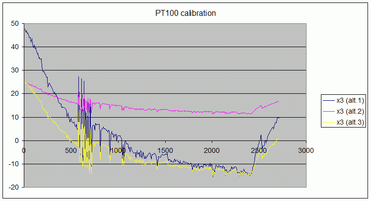
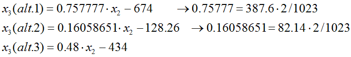
- From Jean
Mootz and Francis Massen's' calibration study we compare two of the
calibration functions. The first one is accurate with negative temperatures,
while the second is applyable with positive values and yields the
correct temperature at start, while the first returns the lowest
temperature that was measured. We therefore propose a third calibration
function that will spread the values all over the operation range.
|
|
2008/06/05
- A few serious issues appeared yesterday
(during the meeting with Francis and the evening team session):
- Hardware:
- The main LUXPAK device still is not
totally stabilized within the polystyrene box ==> the students
already solved this : photos will follow
- Francis is right objecting that the
small stud in front of the HMOS sensor (ozone nose) should be
clipped off in order to liberate the nose. A plastic nug must be
added then to secure the O3-sensor.
- Brian Davis, one of the HALE
participants has suggested to somehow use the heated air from the
ozone-tube to heat the box interior. Good suggestion! We therefore
will not close the O3-sensor box in an air-proof way.
- We already received the NiMH
replacement batteries from CONRAD
electronics.(Thanks for the incredible speed!). However
the NiMH batteries present some disadvantages:
- Weight is still an issue, because
we need to find those grams that Eric Wang needs for other
participants.
- We have no official data about
self-discharge. Francis' experiment shows a loss of 0.32V loss
over 5 days, which does not encourage our optimism, because of
the characteristic discharge graph. The only solution is that
the accus should be recharged just before launch.
- We have no indication about the
conformity to air transportation legagy neither internationally
nor specially for the US for these batteries.
- As ENERGIZER
is one of the HALE sponsors, we had a glance at there products and
found a Li-battery that could be an interesting alternative:
- Product-name : L91
- Voltage : 1.5V
- Capacity : more than 3000mAh
- Wide operation range : -40 ..
60°C
- Weight : 14.5g (we would have a
gain of 164g for LUXPAK !!!!)
- Inner
resistance : 90 to 150 milliohm (dependent on temperature)
- Long shelf life : 15 years !!! (no
need to charge; LUXPAK even could be sealed.)
- CONRAD
electronics : article number : 626830-62
- costs : ~40€ for 8 cells (we
only would need 8 cells to get 12V) We have a gentle donator, so
we can buy 2 sets of those cells, one for test and a seocnd one
for the flight
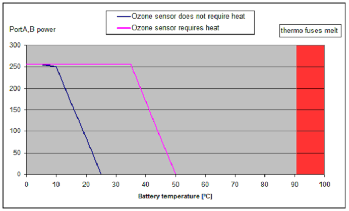
- ==> the different
characteristics under high current load, needs a general
protection: we will add thermo-fuses (cut-off at 90°C) to the
heater circuits. If the batteries run the risk of overheating,
these fuses will dramatically cut the current. Both fuses will
not be placed on the same side of the battery pack and thus will
not react at the same moment. We will not necessarily loose both
heaters in this extreme emergency case.
- ==> we also will move the
box-NTC closer to the batteries to sense the battery heating.
- RCX firmware:
- The selftest-function at program start
may result in a situation, where the Nevada operators won't be able
to start LUXPAK correctly and run the datalogging. The trouble is
that the error-handling just issues the error message on the
display, the LED blinking and the acoustic signal, but does not add
any fail-safe action. ==> we must add a fail-safe mode.
- If we are doing the job with the
ENERGIZER batteries instead of the NiMH, then we will have to add
another temperature control, because those batteries risk to
overheat under high endurance constant 1A current. The idea is:
- since we now get the correct
information about the battery voltage (minus the loss at the
internal RCX rectifier bridge), and we know that most of the
current is drained through resistive loads, the we can deduce
the current from the voltage. If the inner resistance of the
battery drops through the temperature increase, then the
available voltage rises and with the current. If we add a
regulation that will try to maintain the current stable by
reducing the PWM-value, then the battery heating will not be
dangerously important.
- During the high endurance test we
found that the NTC conversion functions as described above present
points of discontinuity tha we absolutely must avoid.
- The hysteresis of 1°C is too wide for
the O3-temperature regulation, resulting in a too slow regulation
frequency
- The threshold of the O3-temperature
regulation must be reduced around 5°C. (We only should avoid frost.
We don't really need higher temperatures.)
- High endurance test :
- Conditions:
- O3-sensor precharged during 1 hour
- -19°C freezing chamber
- 1h30
- PL91 ENERGIZER batteries
- no air pump this time, just the simple
stream that will pass through the O3 sensor system tube
- Results:
- The battery voltage is reduced at
start, because the heater is immediately switched on during 12
minutes. We we consider both 3W heaters as parallel resistances, we
have a total heavy heater resistance R=10Ohms and the heater current
at start is 9.9/10=0.99A. The increase of the voltage after 12
minutes gives us the delta voltage of 11.6-9.9=1.7V and thus an
internal battery resistance of 1.7/0.99=1.7ohm, which is much more
than indicated on the datasheet. However already during the first
12minutes pre-heating phase and surely during the second long-time
heater-on phase the inner resistances drops due to the increase of
the battery temperature. At instant 1h25, where the heater is
shortly switched off, we have only : 11.6-11.05=0.55V difference.
The heater current grows to 11.05/10=1.105A and the inner resistance
is 0.55/1.105=500milliohm. At the end of the experiment the battery
heat was about 50°C.
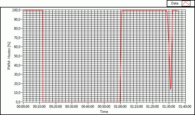
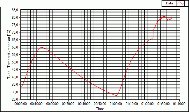
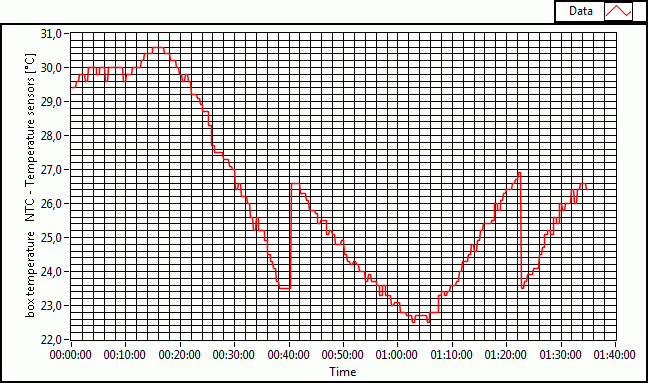
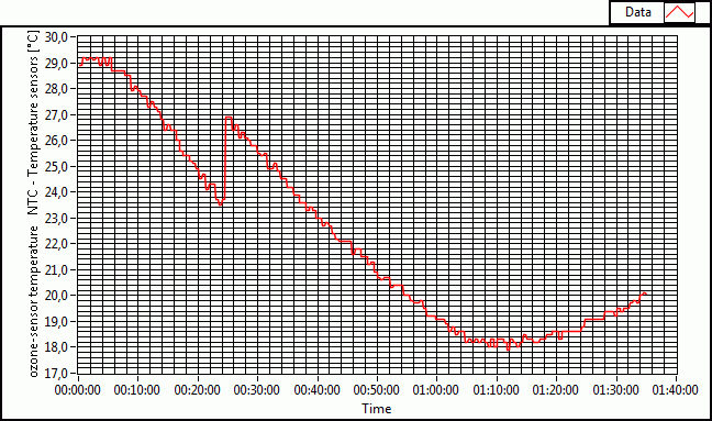
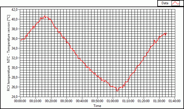
-
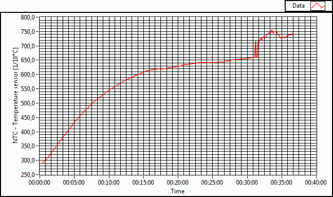
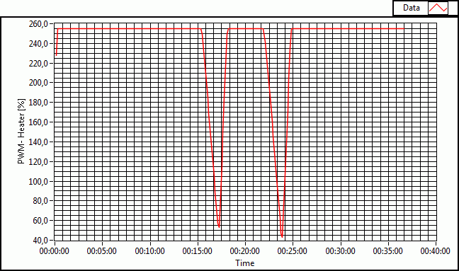
The device temperature
graphs (please ignore the discontinuity, which is due to the error of
the NTC conversion function that will be changed soon.) One can see that
after one operation our the heater regulation is triggered, because the
ozone-sensor temperature droped below 19°C. After 30 minutes the tube
temperature reached the cut-off value of 80°C. The temperature drops
again and the regulation starts to maintain the 80°C in the tube.
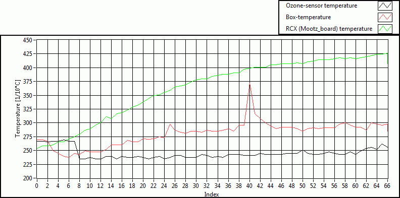
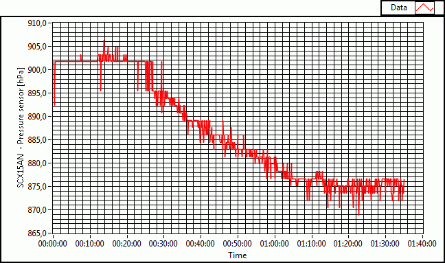
-
The pressure sensor values
-still raw- don't corrolate directly with any of the graphs except the
temperature. As the box was well closed this time, the drop of the
pressure can be seen as a function of air-temperature (although there is
a certain delay between the box temperature and the pressure, probably
due to the pressure sensor tube.) Note that the pressure sensor is
temperature compensated and does not react on changes of the supply
voltage.
-
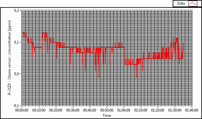
Francis suggested that we could
add a voltage stabilization for the ozone-sensor only. So we powered the
ozone sensor (and later also the Mootz_board) with a regulated voltage of
10.40V. But this does not change the influence of the heater activation to
the ozone sensor values. This is a bizarre behaviour that we cannot easily
explain. So, we can only apply a correction to the measured raw-values after
the flight. Comparably to the PT100, we can recalibrate the O3-sensor and
the back scattered light sensor as well. It must be underlined that the
calibration curve shows that the O3-sensor must be extremely sensitive to
any change at low ozone concentrations.
-
We added the thermo fuses
(cut-off at 91°C+/-3°C). These sensitive devices will be directly glued to
the battery pack on different places.
|
|
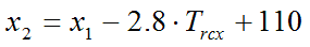
2008/06/09
- We found out that the voltage stabilization
absorbs rapid fluctuations. However, the influence of the heater on the 3
concerned sensors still needs a correction on the raw data.
- ==> Due to the smaller supply-voltage on
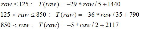
the Mootz_board, the third PT100 calibration function now is changed to:
- x3 = 0.275 * x2 -
231 (the x1 and x2
function are inaltered.)
- Note that this function is much closer to
the one suggested by Jean Mootz and Francis Massen in their calibration
document.
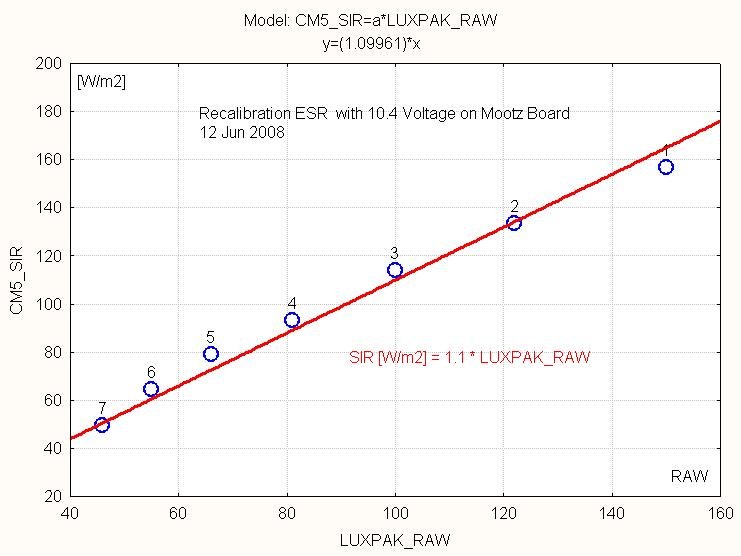
- Another calibration test confirms these
functions:
-
For this experiment one of the
well-calibrated NTC sensors (the formerly called "box temperature
sensor", now the "battery temperature sensor") was placed in
a water-proof small bag together with the PT100. Then both sensors were
plunged in ice-water. At the end of the test, the sensors were taken off and
could heat up to ambient temperature. (Note that we will make a further test
in the freezing chamber on Wednesday to see, how the PT100 reacts then.
-
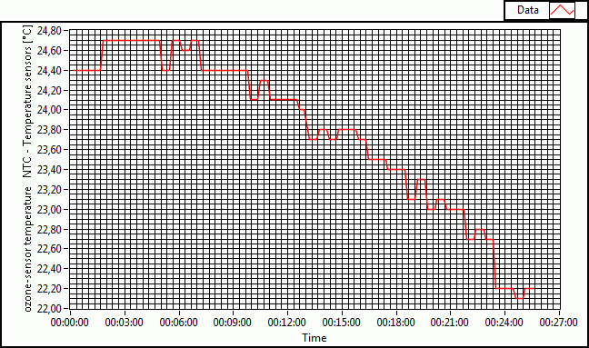
Since we know that the
ozone-sensor is most sensitive for variations at weak ozone-concentrations,
we probably must recalibrate this sensor.
-
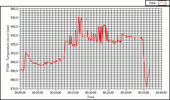
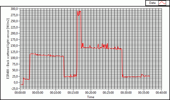
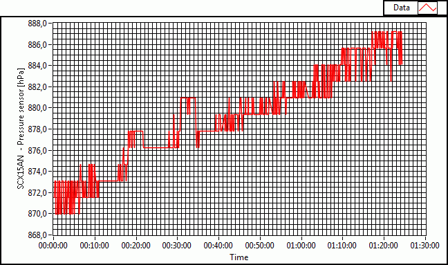
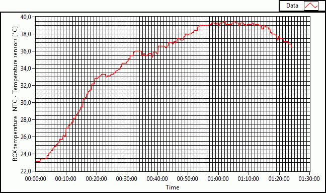
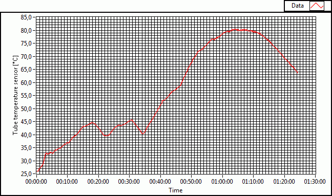
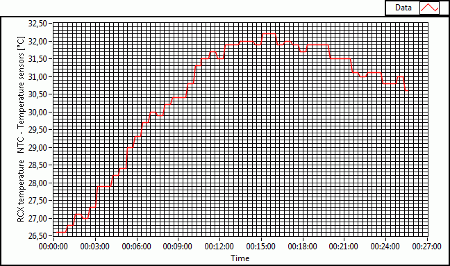
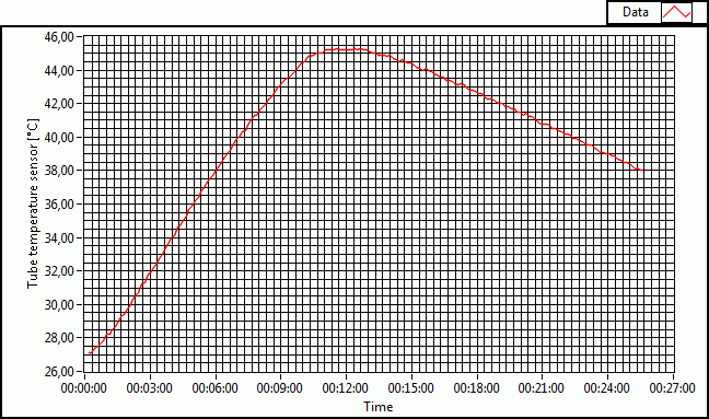
The light sensor also must be
recalibrated. So does the pressure sensor, as can be seen on the following
graphs. Note that the test has been executed with the new RCX firmware that
has a few important changes:
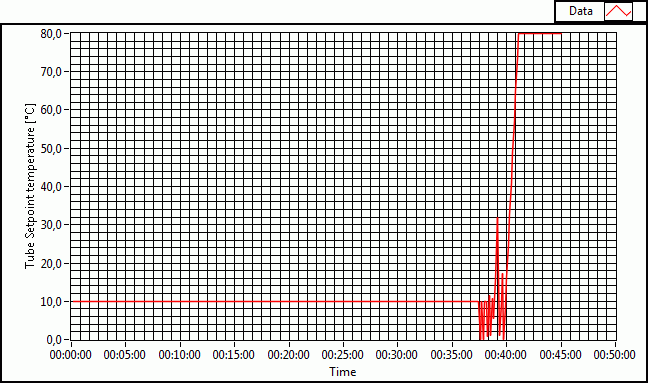
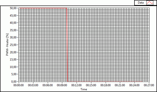
-
The preheating phase only
has 10 minutes anymore. The PWM only works at 50% duty cycle during that
phase. The reason for this is to protect the batteries from overheating,
since the system has to run before with the 800mW heater on during 1hour
(before flight).
-
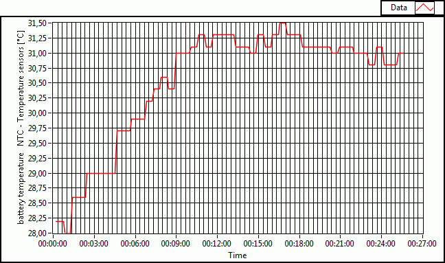
The battery-NTC sensor now
delivers important information about the battery temperature. If it
exceeds a certain threshold, the heater output power is reduced.
-
The firmware shuts down
non-vital functions at low battery to protect SNOOP_LOG
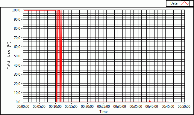
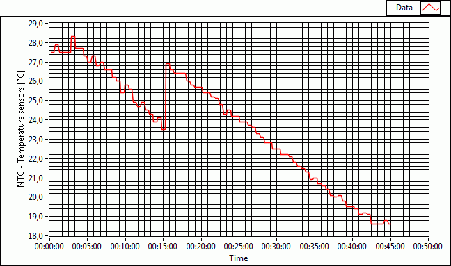
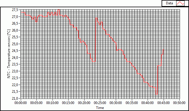
-
During the test the heater was
deliberately switched off by unplugging the wires from the RCX from t=18 to
22minute and t=30 to 33. As can be seen on the graphs, the influence on the
curves is less strong.
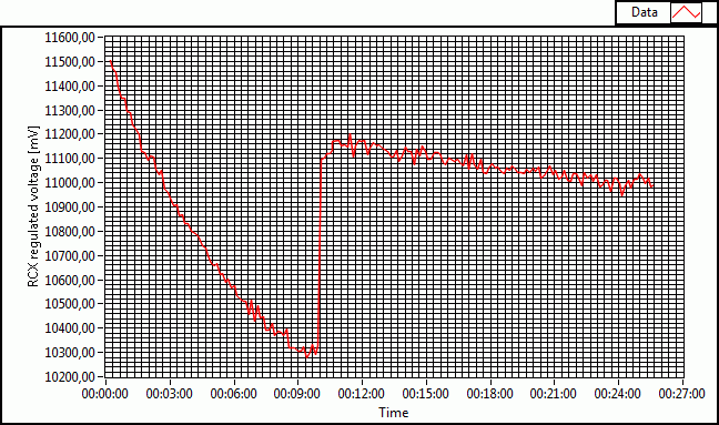
-
At the end of the test the RCX
output driver circuitry regularly reduced the current. This became visible
on the Ampere-meter that was added to the battery cicuit
-
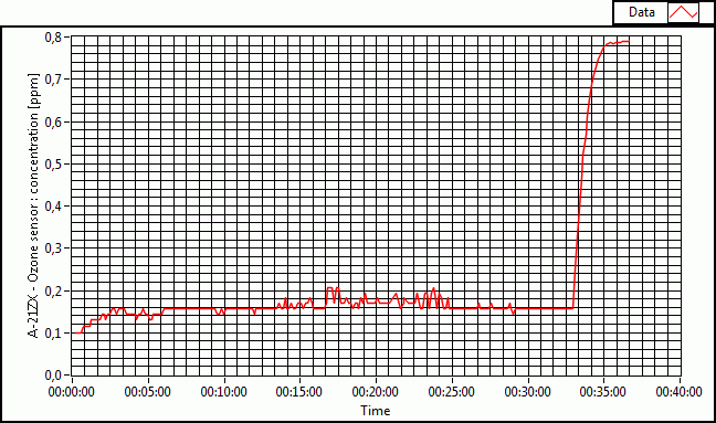
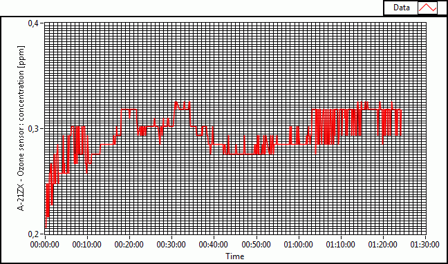
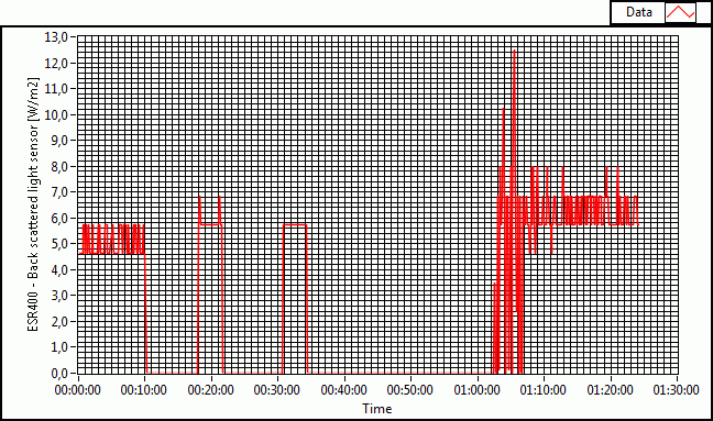
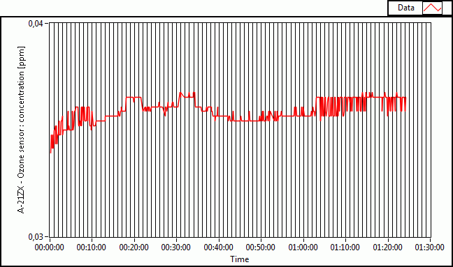
The ozone-concentration
should be 0.03ppm, but is indicated as 0.3ppm on the graph
-
Important
observation: according to the inverse of Francis'
calibration function, 0.03ppm is equivalent to a measured voltage of
0.031V (=16 [raw]). Remember that the raw values extend over the
range 0..1023 proportionally to the voltages 0..2V. Now 0.3ppm
correspond to a measured voltage of 0.074V (=38 [raw]), which means
that in the lower voltages small errors have an impact of factor 10.
This is not the case at higher voltages. Since the deviation must be
considered as an offset of a few mV, we probably can adjust Francis'
calibration function by subtracting the raw offset 22 from the
original data.
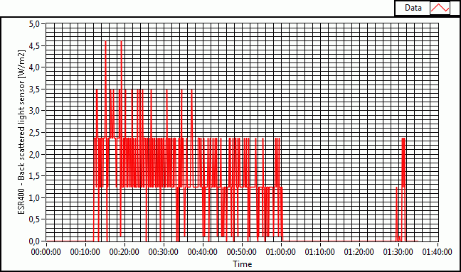
-
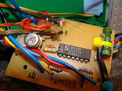
The ESR400 light-sensor is
operated at very weak voltage (irradiance of 10W/m^2 corresponds to a
measured voltage of 46mW according to the calibration function.
However, this is out of the linear range of this sensor (and also of
the LM324 operation amplifier), so that we
can ignore those small values and errors. A throughful
study of errors will be done on the final values.
|
|
|
|
|
2008/06/12
- Our project has found a generous private
sponsor. Thanks a lot!!! The financial support is most welcome.
- CONRAD
electronics offers more detailed datasheet
about the ENERGIZER L91 batteries. And we learn from these papers that the
L91 batteries have a special built-in PTC thermistor that increases the
battery internal resistor as the temperature reaches 85°-95°C. This
represents a very useful protection against overheating, since the current
will be limited at high temperature. However, we will maintain the
additional thermo-fuse protections and the temperature regulation, because
reduced battery inner resistance will cause higher currents through the
RCX... and this will happen already at much lower temperatures. The result
will be current limitation in the RCX output drivers, but also undesired
heating of the RCX interior. If the batteries reach very high temperature,
besides the PTC, the permanent disabling of the heaters -one by one- will
help protecting both the batteries and the RCX.
-
LUXPAK will be closed by Velcro
hook-and-loop fasteners that will be glued to the box. This is an excellent
mechanical way to fix things together that has proven its validity under
extreme conditions. That's why NASA is a big Velcro user.
-
We now started the user guide
paperwork, a second one about the pedagogical aspects and finally on the
control stuff that completes Francis' work on the equipment.
-
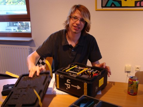
This evening will be the moment
of definite assembly of LUXPAK
-
Paul-Nicolas has already worked
on the logo picture.
|
|
2008/06/13
- The adjusted pressure sensor calibration
function now is : p [hPa] = 1.712 *
RAW_VALUE - 419.44
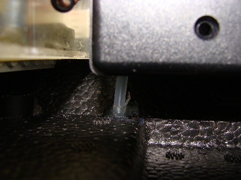
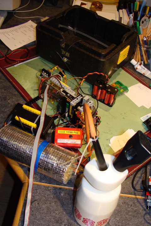
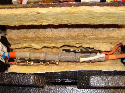
- Here the photos of the final sensor
calibrations:
- with the pump we produce vaccum:
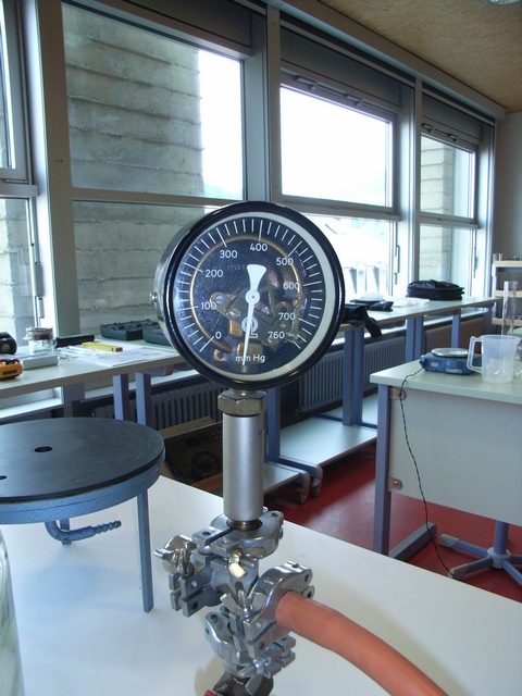
|
|
|
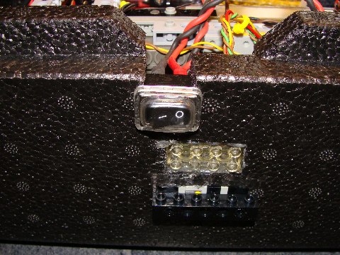
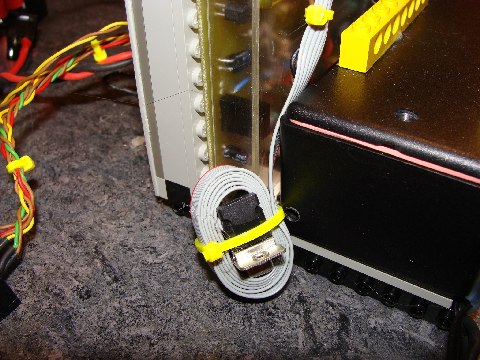
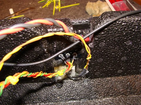
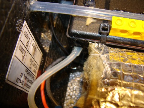
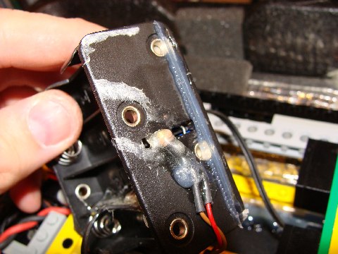
the RCX power plug:
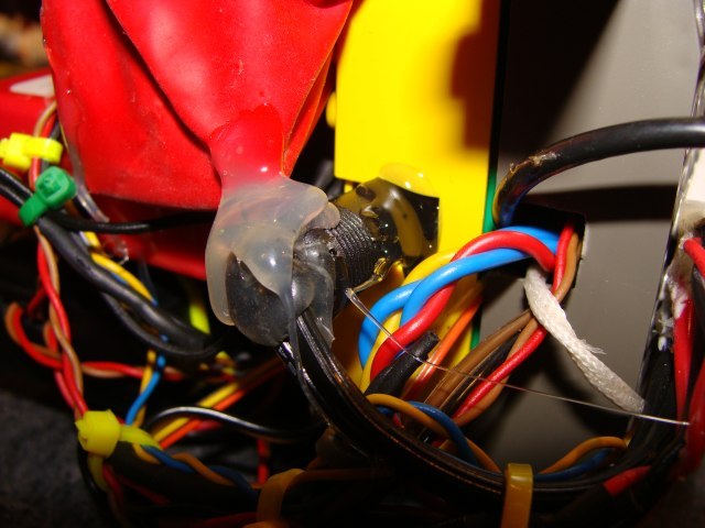
the RS232 cable:
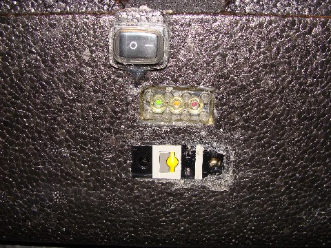
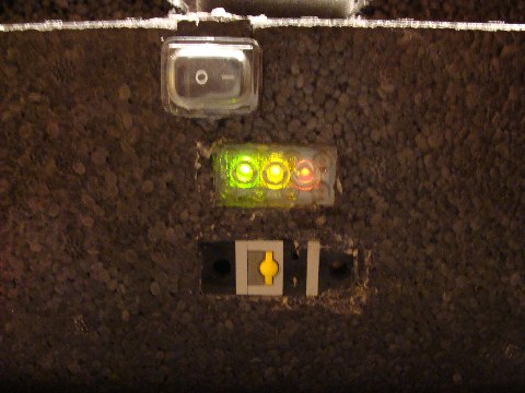
preparing to fix the buttons and
LEDs:
switch, LEDs and RCX touch-sensor
from the rear:
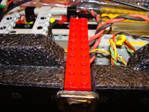
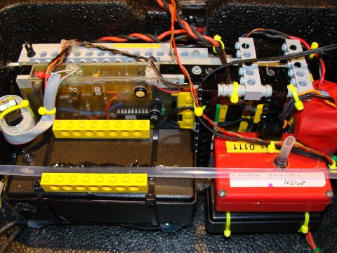
before placing beneath the balloon
tube:
the balloon tube is visible:
the outlet of the ozone-sensor:
the Teflon-balloon-tube is glued
to the ozone-sensor case:
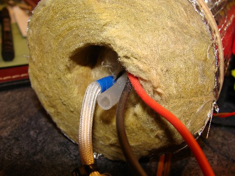
the resistors disappear in the
isolation:
idem:
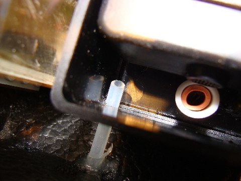
the inlet to the heated tubing:
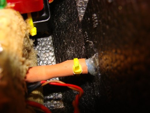
the inlet to the ozone-sensor
case:
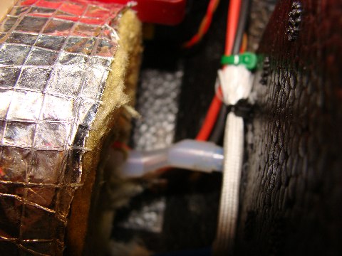
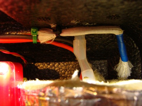
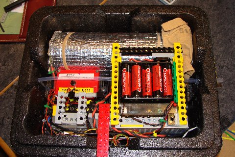
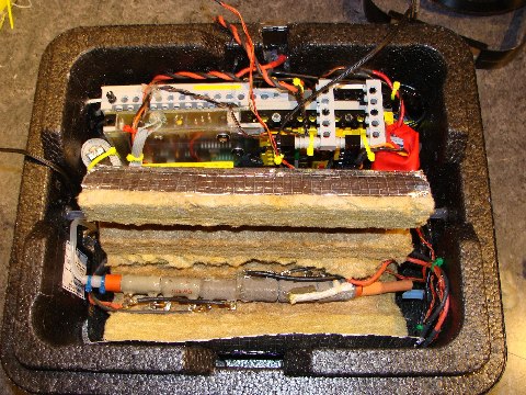
the RS232 cable in the box:
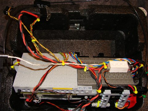
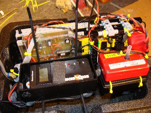
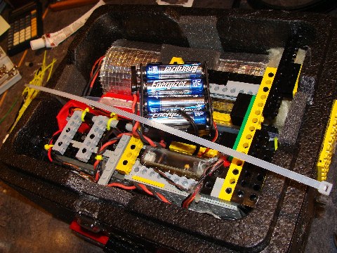
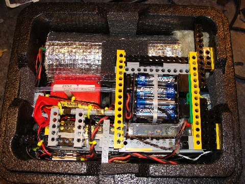
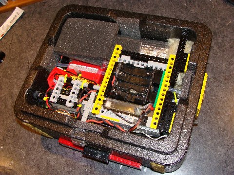
general aspect of the interior
with Erik and Laurent's LEGO construction:
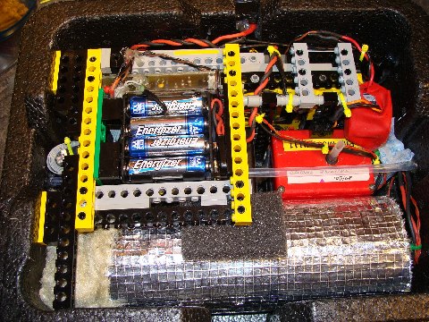
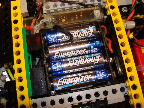
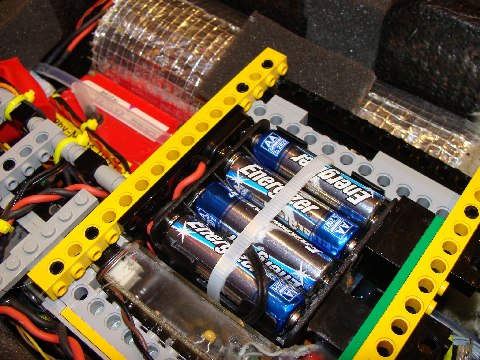
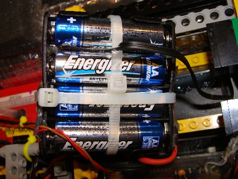
with the batteries:
the communication side:
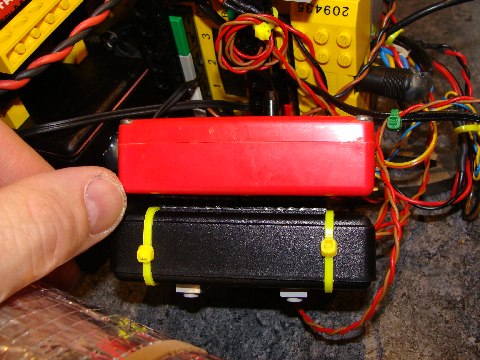
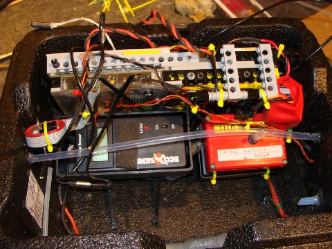
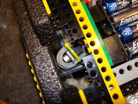
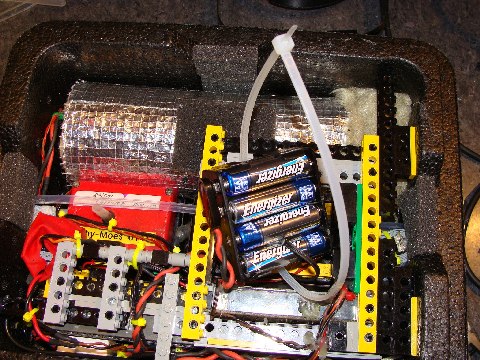
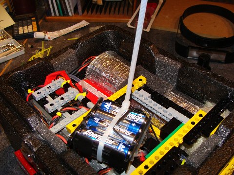
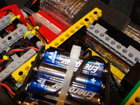
how to install the batteries:
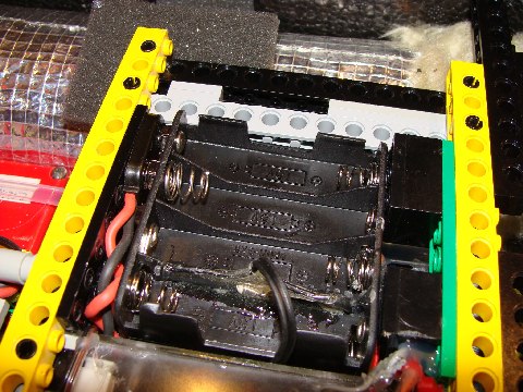
see the thermo fuse on the bottom
of the pack:
... and the thermistor glued to
the outer wall::
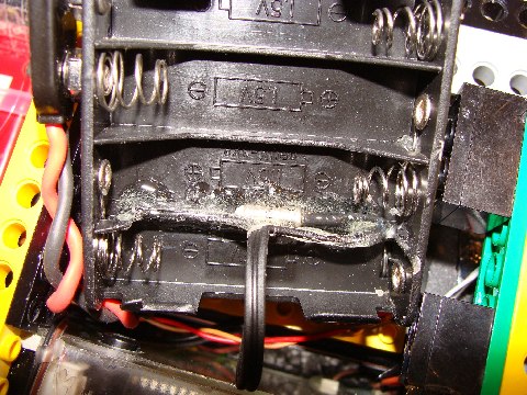
the batteries must be fixed with a
long cable binder:
how this is done:
next step:
one more:
cut the end:
turn it around and place it in the
socket:
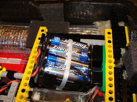
now everthing is well in place:
another view on the whole thing:
Velcro is fastening the top of the
box:
with additional isolation pads:
the LEDs light:
|
|
2008/06/15
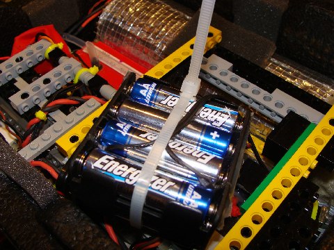
- The batteries need to be fixed with two cable
binders. Otherwise there is a risk that they loosen through vibrations. This
would corrupt the whole mission. The first one absolutely must be strongly
tied. But attention to the seocnd one, not to damage the holder.
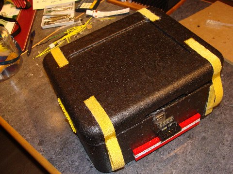
-
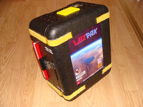
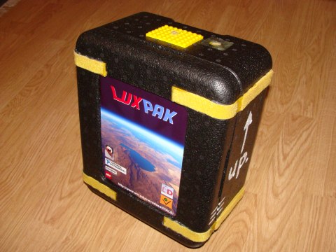
Now LUXPAK has its LOGO, which
was designed by Paul-Nicolas. (He borrowed Eric Wang's photo. (Eric, hope
this is OK.). The Konvikt's and the LCD's logos are well visible and the
sponsors' too. The web-site is indicated to help potential finders to return
the payload to their owners. The container body and the cover have marks
that must be respected. LUXPAK has an orientation that also must be
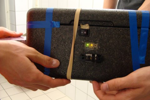
observed.

|
|
|
2008/06/16
|
|
2008/06/17
- The bill
of material is available.
- LUXPAK's transport to Reno will probably be
done via UPS.
|
|
|
2008/06/19
|
|
2008/06/26
- Laurent while preparing the very final test in
the freezing compartment
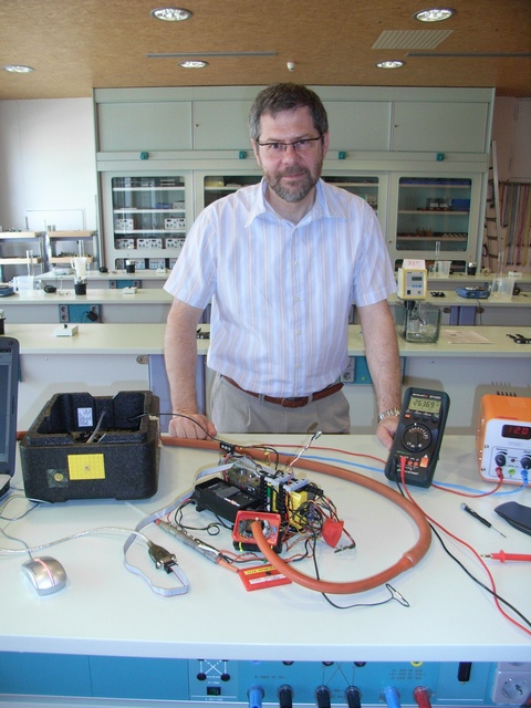
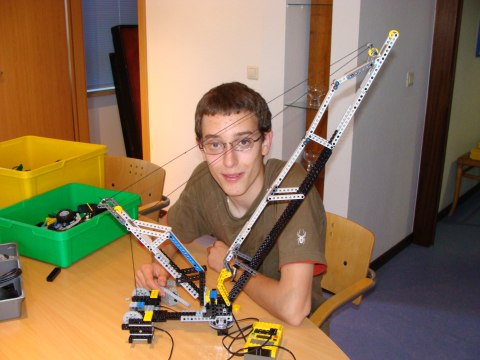
- Eric already passed to his next project a
sophisticated fully automated crane, which definetely has nothing to do with
LUXPAK :)
-
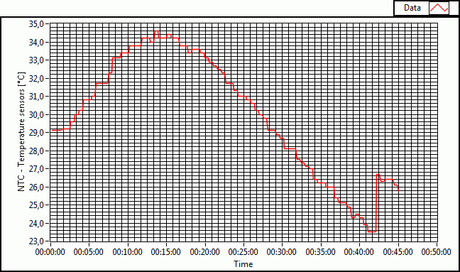
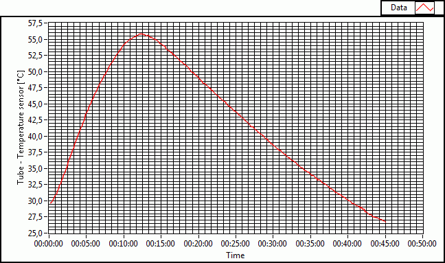
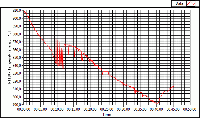
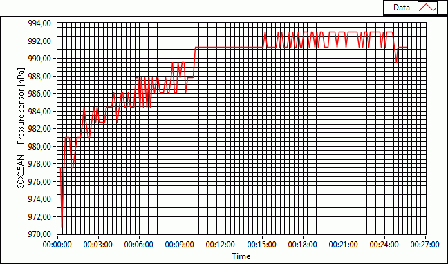
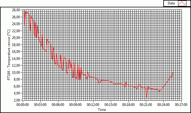
From the data we retain that the
pressure sensor either needs a power-up time or has a certain dependency on
voltage or container temperature variations that we will analyze on the HALE
event data later. The air-temperature gradient is flatter, because most of
the PT100 sensor is placed in the isolation material. Only the very top has
contact to the air.
|
|
2008/07/01
- LUXPAK is being shipped to its destination
Reno NV via UPS. The package should arrive by July 7th.
- We should agree with Francis :-) :
- *** let's hope and pray the Lord:
1. to boost battery-life
2. to create a local short lived stratospheric warming
3. to remove that sand-corn blocking the ozone inlet/outlet channel
4. to make the landing site smooth and spongy
- Perhaps we should add:
|
|
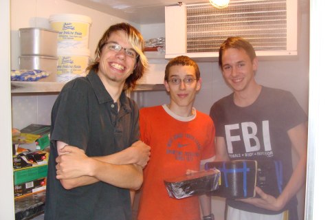
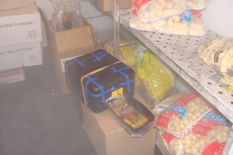
2008/07/26
- HALE launch date has been fixed to July 29th
at dawn likely at location: N 40° 20’ W 119° 20.5'
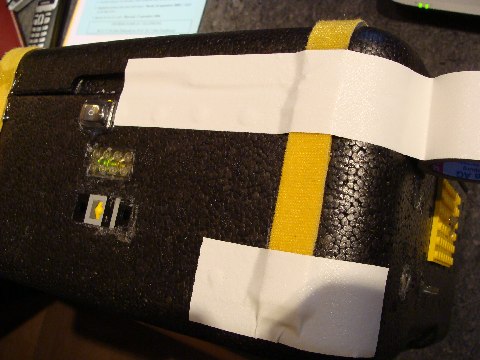
- LUXPAK survived the "horizontal
trip" from Luxembourg to Reno as can be seen on one of Eric's photos
that we borrowed from him:
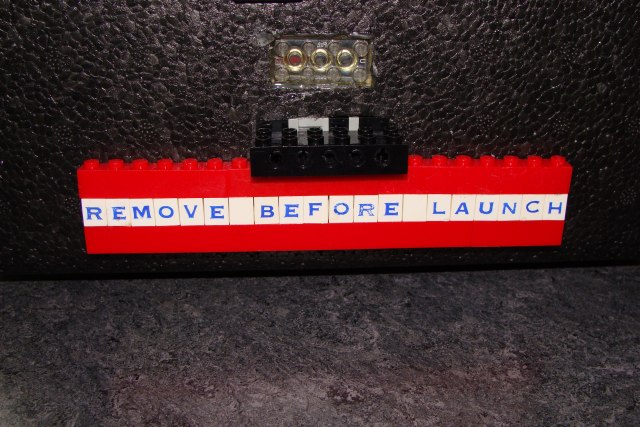
- Hi guys, don't forget to remove both paper
protections, that we placed over the ozone sensor inlet and the outlet
stud, before launching the balloon... and of course the most important
panel "REMOVE BEFORE LAUNCH" !!!!
|
|