![]()
Motor power
Ultimate Robolab allows a better motor speed control. Unlike the standard firmware providing only 8 power-levels, Ultimate Robolab has 32 of them. For various reasons, it has been chosen to have the power-range evolve from 0 to 255 in steps of 8. It is well known among Mindstormers that RCX power-level and motor speed are not proportional. This page tries to investigate the linearity of Ultimate Robolab motor power-levels.
The RCX motor-power non-linearity has its origin in the low frequency of the pulse-width modulated (PWM) signal. Perhaps we should explain the mechanism of motor-control through a PWM. First, let's have a look at a DC-motor being controlled by variable DC voltage. Surely the best web-site about LEGO motors is Philo's. The following graphics are borrowed from this exceptional Master-Mindstormer. (Philo -hope you will enjoy this reproduction -vu?!)
http://philohome.com/motors/motorcomp.htm
|
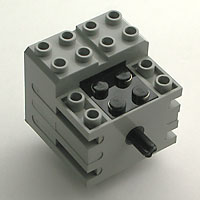
Electric Technic Mini-Motor 9V LEGO Part No. 43362 |
The speed is proportional to the applied voltage. |
Producing different voltages with a micro-controller normally is an easy thing. The trick is to pulse a signal at high frequency at a certain duty-cycle which is the on-time of the signal compared to the whole period-time expressed in %.
The RCX produces such a signal to control the motor-speed.
Suppose that instead of using a motor, we connect the LEGO lamp, which is a pure resistive load, to the RCX, we may observe with an oscilloscope that both the current and the voltage, and thus the dissipated power, follow the rectangular signal shape. The reason for this behavior is the fact that with alternative current at even high frequency, a resistor still follows Ohm's law U=I*R. However, the light intensity -or better the impression our eyes get from the lamp - is directly proportional to the duty cycle. This can be explained by the slowness of our visual sense, which only may react on a limited number of photons received within a certain period.
The motor represents a very different device. Philo shows the motor internals at http://philohome.com/motors/motor.htm . You may recognize there that the most important electric elements are the coils that are used as electro-magnets. The rotational effect is generated through alternating magnetic fields in the motor. For our purpose here, we want to consider the inductance itself rather than the magnetic effect. If an inductance is used with alternative current, the voltage doesn't follow anymore in a proportional way. The non-linearity depends on the characteristics L (inductivity) of the coils expressed in H (Henry) and of course of the signal frequency. Normally a coil has a fix inductivity, but a variable inductance, where the inductance is expressed as:
XL = 2 . p . f . L
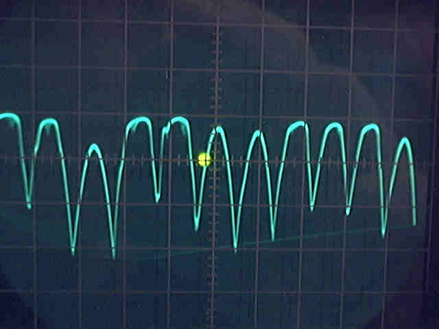
Due to the rotation of the motor-shaft (also called the rotor), the motor-inductance continuously changes in function of the rotation velocity. If you connect a LEGO motor to an oscilloscope and if you turn the shaft, the device generates DC voltage with a half-sinusoidal AC component. As can easily observed, the frequency of the signal is proportional to the rotation speed of the rotor.
Thus, a PWM driven DC motor, must be electrically considered as a coil-system that is exposed to two frequencies. If now we want to have the motor react in a proportional way to the applied PWM duty-cycle, it is necessary to choose fpwm >> frot, since then changes in frot will not affect the inductance too much. In this case we would guarantee a nearly constant inductance.
Normally, in order to provide linearity, PWM frequencies are chosen between 2kHz and 25kHz. But unfortunately, the RCX has no real hardware PWM available to control three motors. Instead the signals are produced by software means. The standard firmware produces different waveforms in function of the motor-power. The signal frequency is 125 Hz (except for motor-power 7, where the frequency is zero).
Waveforms
Standard waveforms ROM located @3fc2 are:
| power 0 | 00000001 |
| power 1 | 00000011 |
| power 2 | 00000111 |
| power 3 | 00001111 |
| power 4 | 00011111 |
| power 5 | 00111111 |
| power 6 | 01111111 |
| power 7 | 11111111 |
What happens during the process?
With the Ultimate Robolab, the waveforms are 4-bytes long, providing a better resolution:
However the signal frequency is not constant anymore :
The following program has been used with a heavy load differential drive (dual drive) robot base equipped with a rotation sensor that has been directly coupled to the motor shaft. It allows us to get a feedback about the linearity. The robot drives at growing speeds during a certain time. The robot speed is continuously computed. The motor-power and the speed are logged.
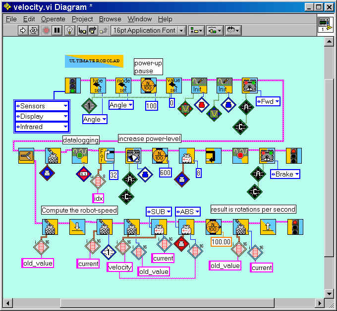
The uploaded data is converted from rotations per second to rpm and brought into relationship:
speed = f (motor-power)
Apparently the robot-base does not move at motor-powers 0..32. The torque must be considered as too weak for the heavy loaded robot base. But, even if there is no direct proportionality between motor-power and speed, a less loaded robot can be perfectly speed-controlled.