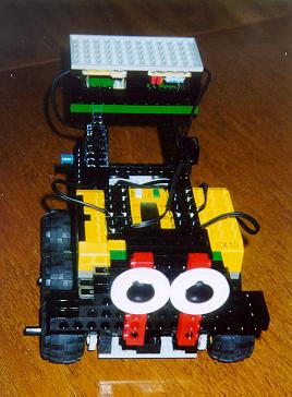
Analog Compass with Robolab 2.5
Last update (13/11/2001)
This was actually a hard challenge: program our analog compass under Robolab 2.5 ! But we got it running.
Here some pictures of the sub.vis. The detail may be downloaded and viewed with Robolab.
The Pewatron analog sensor, which we used for our circuit has two hall-sensors that are connected to port 2 and port 3 of the RCX. Obviously we'll have different value-ranges for both ports due to part-tolerance. So, both signals of the compass should be standardized. The parameters for the standardizing function are set during the calibration. We put the compass on a synchro drive base, far enough from the motors not to be disturbed by the magnetic fields. The motors should be connected to port A and C.
 Sensor Calibration
 |

Continuously read and display the actual heading. |
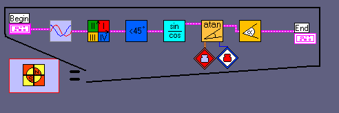
Main program |
Y = A*X + B
during the calibration-time the program fixes the minimum and maximum sensor values:
min1, max1 for signal1 (port 2) and min2, max2 for signal2 (port 3)
then the midth of signal 1 is calculated: midth = (max1 + min1) / 2
now comes A = (max1 - min1) / (max2 - min2) [this is hard stuff, because A is a floating number generally between 0.9 and 1.1 ; the RCX only knows integer numbers, so this floating-point operation has to be emulated ; later the A*X operation has to be emulated too]
B = max1 - A*max2
- standardize
- fix the quadrant (I, II ,III, or IV)
- check if abs(signal1-midth) < abs(signal2-midth), so that the division is less then 100% [the atan-function can only be operated for values between 0 and 100%] - mark this as case 2; if not the values must be exchanged - mark this state as case 1
- calculate the division
- operate the atan-function
- extract the real angle respecting the quadrant and the case
| variable | use | ||||||||
| 0 (red) | argument | ||||||||
| 1 (blue) | function-result | ||||||||
| 2 (yellow) | ANGLE | ||||||||
| 3 | min1, free after calibration | ||||||||
| 4 | max1, free after cal. | ||||||||
| 5 | min2, free after cal. | ||||||||
| 6 | max2, free after cal. | ||||||||
| 7 | d1=(max1-min1)*100,
free after calibration |
||||||||
| 8 | d2=(max2-min2)
free after calibration |
||||||||
| 9 | midth | ||||||||
| 10 | unused | ||||||||
| 11 - 17 | temporary (A*X),
then
|
||||||||
| 18 - 20 | temporary (atan) | ||||||||
| 21 | conditionned signal1 | ||||||||
| 22 | conditionned signal2 | ||||||||
| 30 | B | ||||||||
| 31 | A |
There are many error-sources that intervene in the compass-reading process. We'll discuss some of them in the following growing page-part:
1. Tilt-error
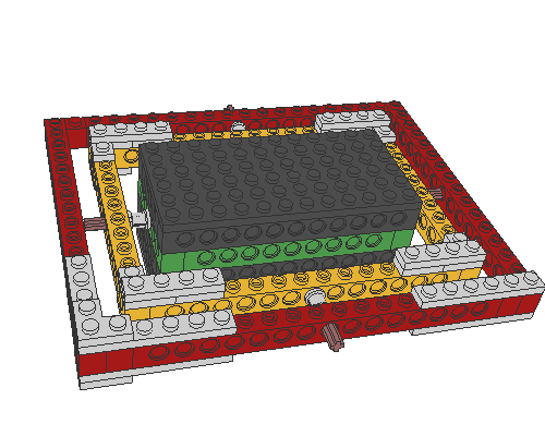
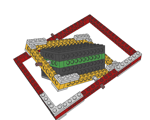
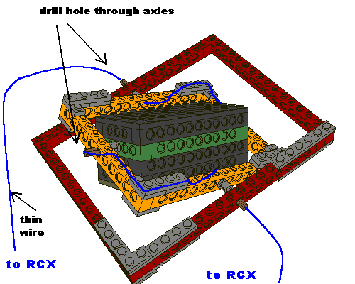
This is the major problem of any electronic compass. The Pewatron analog-sensor is very sensitive to this kind of influence. You may compensate the errors by measuring the inclination and deducing some complicated correction-function. We propose a mechanical solution:
The compass is fixed at a mobile frame that allows the compass to always stay in a horizontal position. This makes the compass independent to inclination. Note that very thin wires have to be used to avoid traction-influences. Drill a hole through the four axles (with studs) and pass the wires through them as shown.
 |
 |
 |
2. Swing errors
As we showed already earlier, for mechanical reasons the Pewatron-compass may return readings that swing around the exact values at a frequency of about 2.875 Hz. The swinging effect is damped typically after 2 seconds.
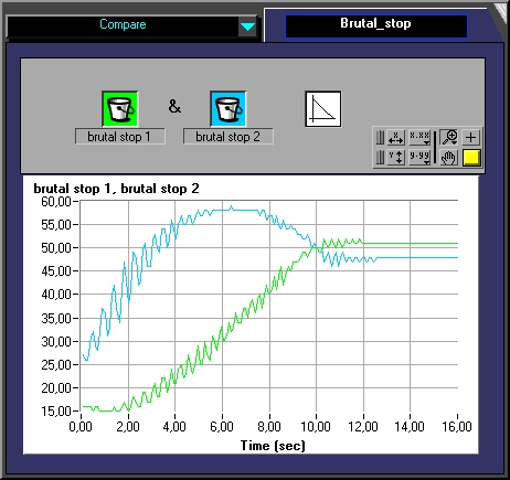
So, especially during motion a filtering-procedure should be active.
Some tests showed that the program produces 47 compass-readings during 10 seconds (4.7 Hz). This frequency is slightly slower than twice the swinging-frequency, so that the main sampling rule:
fsampling > 2 * finformation is NOT fulfilled.
Thus it makes no sense to apply a filtering-procedure to the final compass-reading. Instead the signals could be damped through capacitors added to the circuit, or - if a software-solution is preferred - a filtering could be applied immediatly to the signal when being read by the RCX. The RCX has a high sampling rate, compared to the swinging frequency. As often pointed out, an active sensor is powered during 3ms then read during 0.1ms, which represents a sampling-rate of about 300 Hz. The damping effect is produced by operating a weighted average computation to the data. A task is added which has nothing else to do but sample and do the averages. The standardization-sub.vi has to changed a bit.
 Read and display continuously the compass-value in °
 |
 |
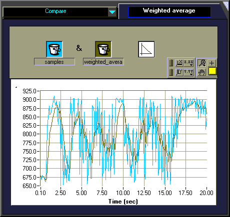
NOTE that now the variables 3, 4, 7, 8, 10 are occupied for average-computation. Only variables 5 and 6 remain free for use after calibration.
3. Non-orthogonality
Again this is a typical electronic compass problem. The orientation in the earth magnetic field is mostly yielded through two components Vx and Vy vvhich are measured by identical magnetic sensors placed orthogonally. In reality the angle between the two sensors is 90 ± b as shown.
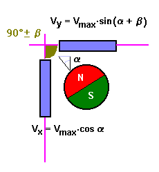
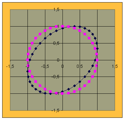
To demonstrate the influence of b on sensor-readings let's take an example:
b = 20°
__________ = correct values
__________ = erroneous values
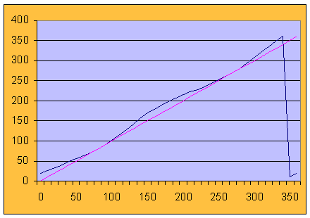
The Lissajou-graphs, which are built of all the points M[cosa, sin(a+b)] look like:
From trigonometry we know the relationship:
sin(a+b) = sina cosb + cosa sinb
Vy, corrected = Vmax sina
Vy, corrected = Vy / cosb - Vx tanb |
NOTE that for the Pewatron-compass the pitch of each sensor-part has no influence on the azimuth-yielding, as every sensor-reading is affected equally.
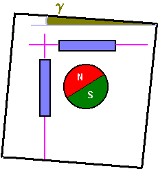
4. Non-parallelism errors
This error-source is the simplest to be eliminated. There is a certain declination from the real azimuth which is independant of the angle a. The cause is the position of the compass to the supporting frame. To correct the errors, the values only have to be changed by translation.
azimuthcorrected = azimuthread ± g
5. Metallic and magnetic interferences
This kind of errors may appear in the case of asymetrical response of one (or both) magnetic field sensors. Suppose the sensor returns a higher voltage when influenced by the NS-direction than in the opposite case. This may be the case if there are magnetic or metallic influences around the sensor. Effects known as "hard iron" effects are caused by magnetized material at a fixed relative position in proximity to the sensor. "Soft iron effects" occur when the earth magnetic field is distorted by ferrous objects.
These effects produce sometimes unexpected changes of the Lissajou-shapes, if these graphs are used as diagnostic instruments.
6. Balance errors
These very special errors of the Pewatron-compass are related to the little swinging magnet inside of the chip. Like every mechanical compass, the magnet holds the earth N-S direction, when the frame is turned around. Gravitational forces act on a not perfectly balanced magnetic disk, causing distortions of the response.
7. How to handle compass-errors
example: see Compass-Rover