Robo-Soccer Journal
last update : 25/02/02
29/01/02
This will now be our major project for the second semester of 2001/2002.
The aim is to make two semi-autonomous LEGO-Mindstorms robots play soccer in a given field of 1.20 m x 1.60 m.
Most of the mobile robotics professionals and amateurs know about the difficulties which appear in this project. You'll have to deal with game strategies, speed, collision-avoidance a.s.o.
Primitive robots might possibly play the game, but there is too much random, which will surely make them loose. This is of course not compatible with one of the aims of playing soccer that is to win ! You'd have a great advantage if the soccer player knew :
So again we have to deal with the positioning problem.
Our solution will be a global positioning system based on the LEGO camera which is fixed at the top of 4 wooden sticks. Thus it will survey the whole game and find the positions of both mobile robots and the ball. A special program will continuously analyze the pictures, then send the coordinates and perhaps other data like current direction and velocity to the two RCXs via IR-communication.
Based on this information each mobile robot should then be able to play soccer according to the strategy of choice.
Preliminary problems to solve:
30/01/02
01/02/02
04/02/02 In the field
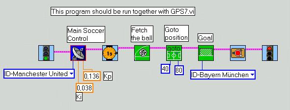
The first tests with a real robot-soccer-player was done with the test-program Soccer2.vi.
You'll recognize the subsumption architecture and lots of new sub.vis which all may downloaded here as Robolab-libraries :
Robo-soccer, Subsumption architecture, Camera_GPS. (versions 4/2/02)
Here some pictures of the most important vis.
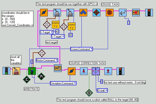
Yes, we've designed a simple FOR-NEXT-loop.
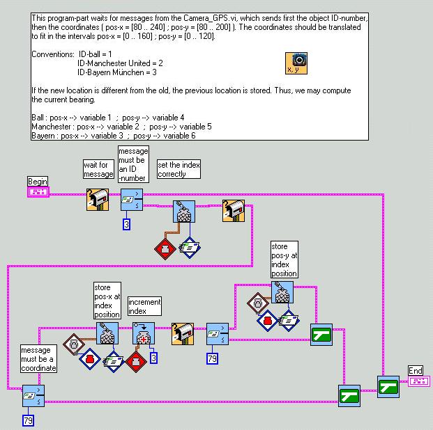
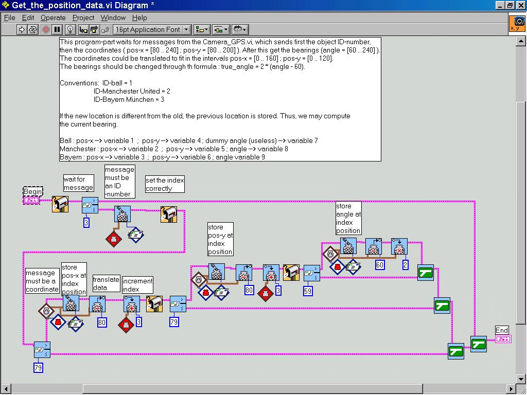
During the first tests all went well. The coordinates arrive from the GPS3.vi. As you can see, the course is only adjusted, when there has been an update with new coordinates AND when these are different from the previous ones. Only with this information the robot is able to find its bearing, for it actually needs two distinct points to do so. Without correct bearing, the course may not be corrected properly.
VARIABLE LIST
| 0 Red | Index |
| 1 Blue | X_Ball |
| 2 Yellow | X_Manchester |
| 3 (user) | X_Bayern |
| 4 | Y_Ball |
| 5 | Y_Manchester |
| 6 | Y_Bayern |
| 7 | Old_X |
| 8 | Old_Y |
| 9 | Target_X |
| 10 | Target_Y |
| 11 | Motor_Command |
| 12 | Cruise_Command |
| 13 | Deviation_Command |
| 14 | Bumper_Command
(for later use) |
| 15 | BEARING |
| 16 | HEADING |
| 17 | Deviation |
| 18 | needed in Atan-function |
| 19 | idem |
| 20 | idem |
| 21 | DELTA_X |
| 22 | DELTA_Y |
| 23 | Allow_Course_adjusting_Flag |
| 24 | Target_Not_Reached_Flag |
| 25 | unused |
| 26 | temp2 |
| 27 | temp |
| 28 | case |
| 29 | Quadrant |
| 30 | dx |
| 31 | dy |
05/02/02
The general idea was to fix the robot's (or the ball's) position through the center of mass-coordinates which are computed in the Camera_GPS programs. This is done very well ! The communication to the mobile robots works well too. But: real world is not ideal world !
As we could probably have expected: serious problems occured in the BEARING-fixing task.
The planned strategy was on the robot-side to update the current position only if it had changed more than a certain tolerance.
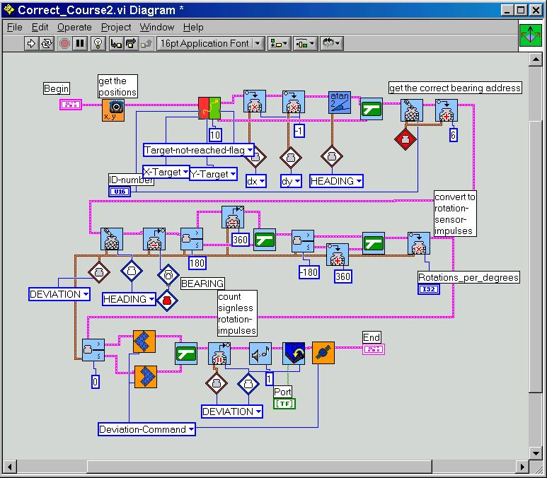
From the division :

we can easily extract the current bearing. The new heading is computed and it is checked, if the robot has already reached the target.
The robot fulfills then a rotation around its central axes (which should be the center of mass of the camera-observed robot-shape) to compensate the course deviation. So, in theory, during the turning the center of mass does not move.
In reality however, the camera-GPS-system registers a motion of the central point during rotation, for several reasons:
So, what did we observe? The robot was travelling around and operated unexpected rotations. But, it constantly moved around the target, never reaching it.
7/2/2002
We detected another problem of the programs GPS3.vi and Soccer2.vi :
By the way, a further Camera_GPS version could include the possibility to flip and mirror the final blop-image. This would make human interpretation easier, since the orientation of the on-screen cartesian system differs from that in reality.
During the team-discussion about this problem there were several proposals:
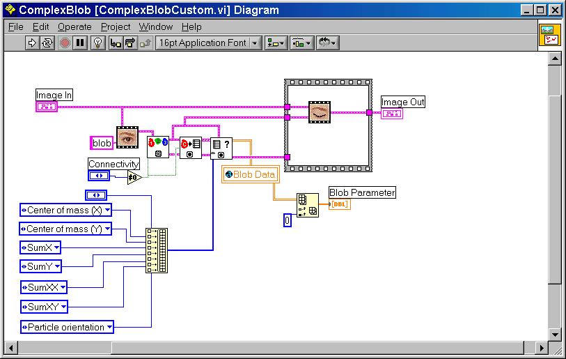
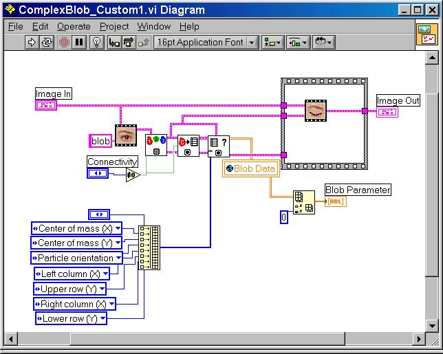
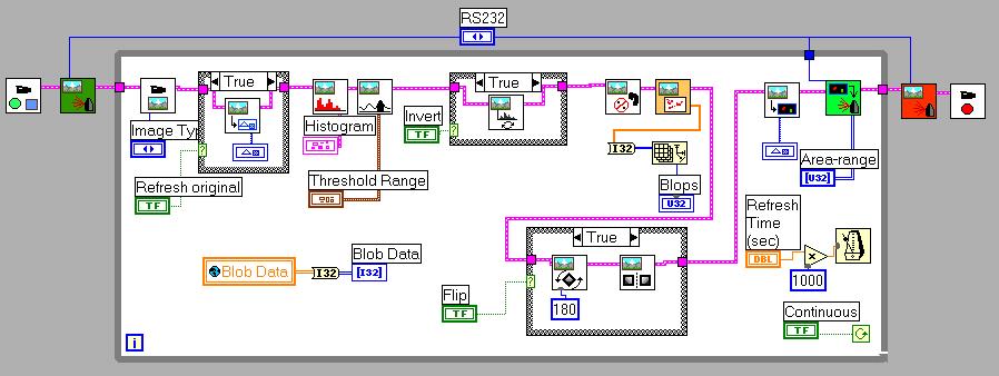
The IMAQ ComplexMeasure.vi (more than the IMAQ ComplexParticle.vi) from the Robolab ComplexBlop.vi permit to extract more information than only the blop-area. There is a longer list of data among which you find : particle orientation, number of holes, center of mass, Sx, Sy, Sx2, Sxy ...
Here a picture of the customized ComplexBlop.vi which enables the extraction of the additional data:
18/2/2002
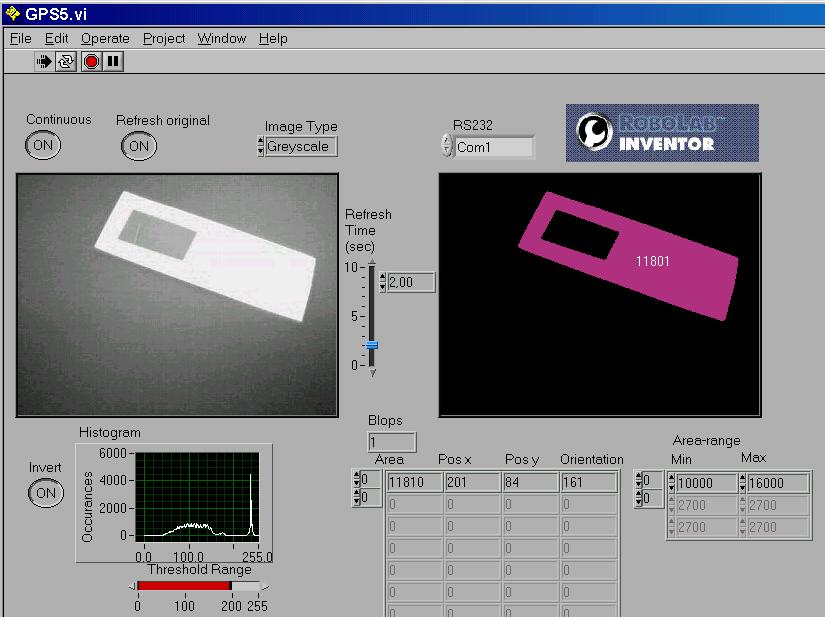
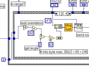
It appears that the particle orientation yields only angles between 0 and 180 degrees. To make a correct bearing-decision possible we add a particle-hole to the observed object. In this case the center of mass ( G ) and the center of the particle ( C ) - defined as the center of the global rectangle - are no longer identical. Thus we may decide whether the center of mass is situated above or below the particle-center.
|
|
|
|
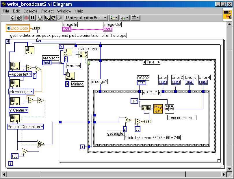
This leads to the altered GPS5.vi which uses the ComplexBlob_Custom1.vi and the write_broadcast2.vi .
It may be tested with the read_and_display_angle.vi equipped with the Get_the_position_data.vi.
19/2/2002
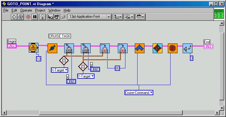
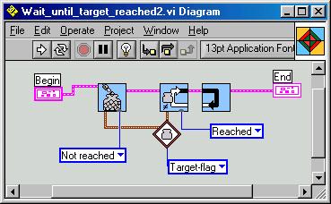
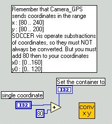
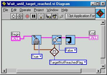
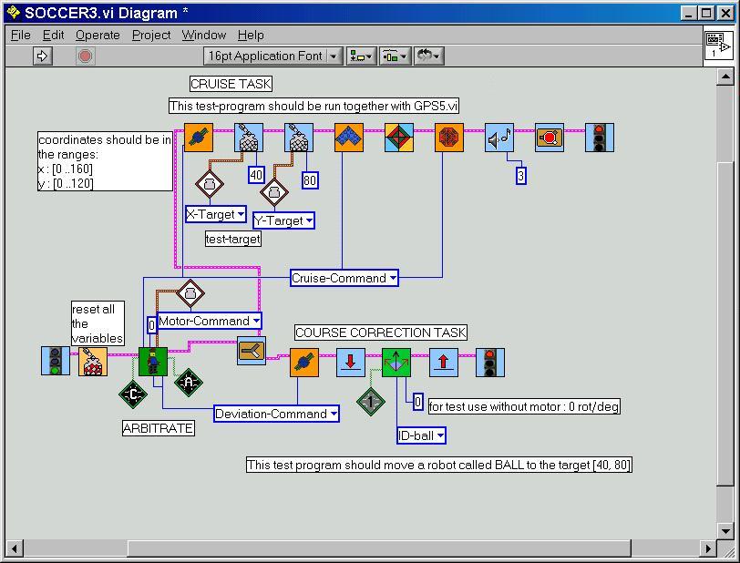
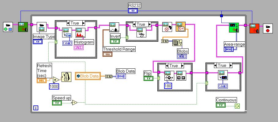
Here now the GPS6.vi which allows flipping of the blob-picture for better readability. Note that the Robolab-original Rotate.vi has a small bug that we have corrected : the designers have forgotten the connection to the flipping angle. The write_broadcast3.vi has a slight change in the angle computation due to the different cartesian orientations. Soccer3.vi allows a first alone robot to reach the target-point [40,80]. It uses the Wait_until_target_reached2.vi, the Correct_course2.vi, the Motion_and_target_test2.vi and the Get_the_position_data.vi from above.
Note that we have a different variable-list now and that the coordinates are immediately converted to fit in the range [0..160] resp. [0..120]. The angle is returned in a 2° resolution.
GPS6.vi :
 the
write_broadcast3.vi changes
the
write_broadcast3.vi changes
23/02/02
The tests with the new programs have been successful. The mobile robot immediately took the direction to the target, but oscillated around the correct course. At every course adjusting the robot overshot a lot.
The causes:
The solutions:
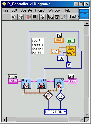
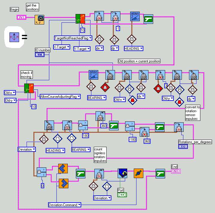
Here a major transformation to the Correct-course2.vi:
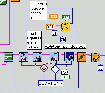
GPS7.vi with an additional switch looks like:
Where Conv_dec_to_quotient.vi is a special Labview-routine to convert decimal values to a division of integer numbers needed to scale the rotation-value.
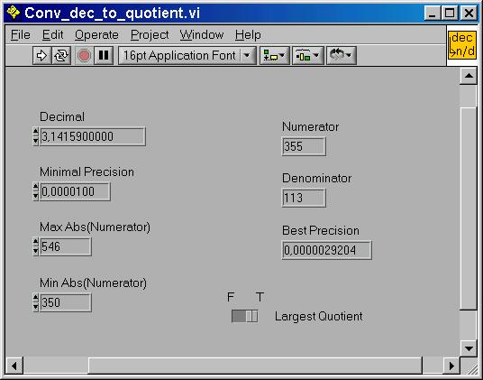
a ~= n / d, a: decimal; numerator, denominator: integer
Example:
You want to scale the contents of a variable x by factor a=3.14159. This is difficult with the RCX, which allows only integer operations. The trick is to find the two numbers n, d, to multiply x by n and divide by d. You must observe not to trepass the 32767 (resp. -32768) integer-limits while multiplying.
The accuracy depends on the range of x and of course the values n and d. The higher the value n, the more accurate the scaling will be. By multiplying the decimal-part of x is converted to an integer part.
Let x be an integer of the range [-60,60]. The maximum absolute numerator is 32767 / 60 = 546. Our desired precision is 1E-5. We want the numerator as high as possible, so we set the lower limit to 350 and the switch to largest quotient. The program issues the values n=355 and d=113 as shown.
Test with x=57 :
y = a . x = 3.14159 . 57 = 179.07063
y' = n . x / d = 355 . 57 / 113 = 20235 / 113 = 179.0708
NOTE : this LABVIEW-routine acts on constants only. It will NOT be included in the RCX-program. But it makes constant scaling easy. The program notifies by an error-message if no quotient was found. If you include the program as sub.vi in an Robolab program this will not stop downloading. But you'll know that your constants are wrong.
25/02/02
The tests with this altered course correcting task shows that the oscillations can be reduced. Now the robot reaches its target much quicker than in the previous experiments. But some unexpected behaviour has still appeared.
This picture illustrates well the sampling problem. Over a certain limit the sampled values do no longer correspond to the original signal. The information gets lost.
The sampling frequency should be at least twice the signal frequency.
In our case of a linear Lego-robot motion at a speed of about 0.4 m/sec, the camera-GPS sampling rate is largely sufficient. But as pointed out, if rotating this is not true.
Here a graphical analysis of the error-sources :
There are actually two major problems:
where W is the heading, x the bearing, e the course deviation, y the controller output (in rotation-pulses). Note that we omitted the load which acts on the final knot.
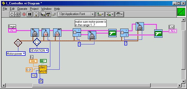
The process might be improved through an additional I(integrate)-controller, so that we are in front of a real PI-controller. In the case of an I-controller, the variations of the controller-output are proportional to the control-error. This is not the usual definition, since it is mostly difficult to influence the derivate of the controller-output directly, but the reasonment is equivalent to saying that the controller-output is proportional to the accumulated error. Considered in that way, the implementation is not complicated, since the motor-speed must only be proportional to the course-deviation. Thus, a large deviation will produce a rapid course-correction and a small deviation a slow correction. The non-standard use makes the tuning of the PI-controller a bit tricky. The best procedure is to follow parts of the Zeigler-Nichols technique and the try-and-error technique:
There exists a huge number of interesting web-sites dealing with the PID technique. There is one particular site which explains the implementation under LEGO-Mindstorms : Using a PID-based Technique For Competitive Odometry and Dead-Reckoning. You'll get some basics at Tuning fundamentals and Back to Basics.
By the way, some other interesting sites around our project here: Camera Positioning, Soccer playing, a master thesis about robo-soccer, Picture handling, some Robolab-links, Robolab in school (German).
26/02/02 FOR SERVER-MEMORY REASONS, SOME PREPLIMINARY SUB.VI -LINKS ARE DEFINITELY BROKEN, YOU'LL FIND THE MAIN DEFINITE FILES SOON IN THE DOWNLOAD AREA.
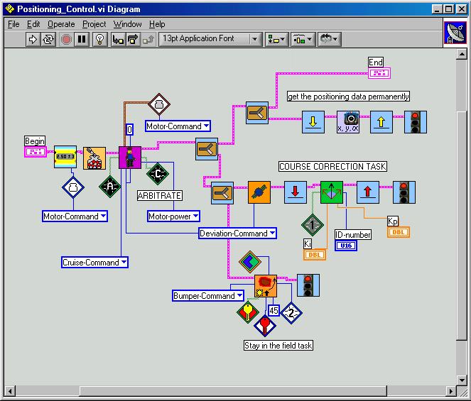
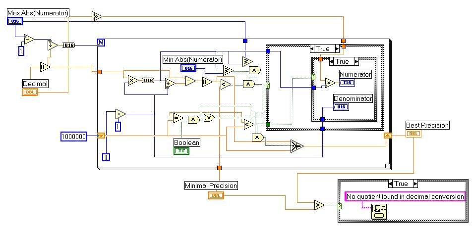
Here now the implementation :