Gyroscope project : Journal
- March 2001
- Decision to buy the piezoelectric gyro from IKARUS.
This gyro must be addressed using R/C servo communication.
- 26/3/01 - 30/03/01
- Building a pulse generator for R/C servos following
the circuit from Gordon McCOMB, The Robot Builder's Bonanza,
USA, 2001, ISBN 0-07-136296-7, p. 305ff.
- Building Ralph Hempel's R/C Servo
Interface for the RCX
- Installing legOS
for advanced programming (tests with 0 ... 255 motorpower-levels instead
of traditionnal 0 ... 7)
- First tests of the gyro using the servo pulse
generator and a R/C servo--> gyro works perfectly
- First tests of the servo interface to the RCX. The
problem of working with R/C servos is that they must be addressed with a
1 - 2 ms positive pulse. The pause between the pulses is irrelevant for
the information, it must however stay between about 14 - 25 ms.
Ralph Hempel's interface and the RCX platform allow
only two states:
- motor power is set to 6: this causes the RCX to
send a positive pulse of 7 msec and a 0-pulse for 1 msec. The interface
inverts the signal.
- motor power 5: 6 msec HIGH-state; 2 msec LOW-state
The programmer has to observe the turning speed of the
servo, or -as overkill- to add angle-reading for exact adjusting.
- Tests with legOS and the following program showed
that the minimum pulse is 1 msec, even if the incrementing is less than 1
msec:
/* servo.c*/
#include <unistd.h>
#include <dmotor.h>
#include <conio.h>
int main(int argc,char **argv)
{
int k;
/*start the motor at power 0*/
  motor_a_speed(0);
  motor_a_dir(fwd);
  msleep(1000);
  cls();
  lcd_int(0);
/*speed up gradually and display value*/
  for(k=0;k<=MAX_SPEED;k++)
     {
       /*speed the motor up a notch*/
       motor_a_speed(k);
	   lcd_int(k);
       /*wait a second to observe*/
       msleep(1000);
     }
  motor_a_dir(off);
  cls();
  return(0);
}
|
Conclusions: there is no possibility to send a pulse
between 1 and 2 msec using the RCX with legOS or the standard firmware. We'll have to design an own interface.
10/4/2001
Andreas Peter has designed a Two
RC Servo Motors Interface to the RCX. He has some very usefull ideas!
Perhaps he could give us the schematics and the PIC-program? We'll ask him.
13/4/2001
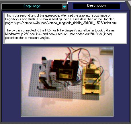
We contacted the manufacturer of the IKARUS Gyro, but the
details we got about the sensor are nevertheless scarce. After a short analyses, it
becomes obvious, that the brain of the gyro is a PIC 16C711. This PIC has a
build-in A/C converter. The conditioned information from the TOKIN ceramic
sensor must enter the PIC somewhere. We found that it is actually Pin 11 of the
PIC. So we tried to buffer the signal first to our lab-instruments, then to the
RCX via Mike
Gasperi's RCX-input-buffer. (The 30mA current from an RCX-input is
not sufficient to drive the gyro. So an external battery is needed). Don't use
an RCX-motor output!! Because of ground-problems.
The gyro was mounted on the RCX (It is possible to stick
it between two Lego-bricks!) Gyro-sensibility manually to 100%. We chose our direction-master (I) for the tests.
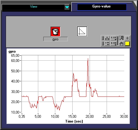
We programmed some heading changes and stored the data in the memory through
datalogging. We captured the values towards the PC. The heading is
expressed in degrees, dH/dt is the derivative of the heading through
time. The gyro values are raw values from 0..1023. To fit them in the graphics,
we used the formula y=800-gyro_raw.
--> The gyro gives the derivate of the
heading. Some mathematical transformation has to be done. First the zero-point
has to be detected, then probably a proportional adjusting.
17/4/2001
If the gyro is used as designed by the manufacturer, there
is NO need to build an own servo-interface, since Ralph Hempel's interface may
be used on his PBForth platform. PBForth has two keywords SERVO_INIT and
SERVO_KEY to generate any pulse width from 0.50 to 2.50 ms. It's even possible
to drive two servos from one output (by setting the mode-option and replaceing
the Graetz-diode-bridge by an unilateral circuit. (book: 'Extreme Mindstorms'
p.313)
20/5/2001
After a longer pause we work again on this project.
We operated some additional tests using the following
device. The rotation sensor is connected to RCX input 2 :
RESULTS: SEE
THE ROBOLAB-FILES
30/10/01
We are working now with Robolab
2.5 ! This marvelous program has some very interesting features such
as the possibility to integrate textual program-parts. Many things are improved
from the previous version, but there remain some bugs, specially in the
graphical part of the compute-area. Nevertheless, we are delighted with all
these new possibilities. This software makes robot-programming reachable for
secundary students !
 Main
Page
Main
Page