|
JOURNAL (very
long) go to journal
(II) go to journal
(III)
|
most important
links
|
|
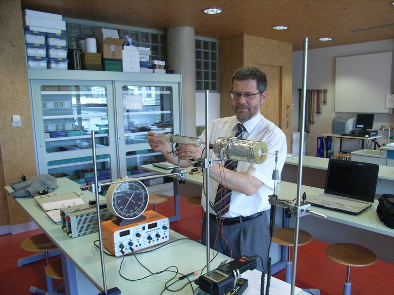
2008/04/09
-
We
have been invited by Dr.
Eric Wang to participate in the H.A.L.E.
contest. The challenge consists
of designing a payload for a meteorological balloon that will be launched to
the stratosphere at an altitude of 27-34km. The purpose is to either carry
along a camera or a device for scientific experiments.
-
We
choose meteorological experiments.
-
At
this point, the team is composed of Claude Baumann, Francis
Massen and a group of LEGO robotics experienced students.
-
Our
ideas now have been refined and we will come along with the following draft
project:
- device-name:
“LUXPAK”
- weight:
less than 1kg
- package:
- size:
should not exceed 40cm*20cm*20cm
- outer
box : polystyrene (Styrodur) with reflective wrapping for thermal
insulation
- inner
box : plastic (undefined yet), contains all electronics parts
- inner
box will be fixed to outer one with a shock absorbing structure made
of LEGO pieces
- purpose:
- measure
ozone-concentration, air-pressure, temperature (inside/outside),
reflected light from earth during the ascension from ground to
stratosphere, optionally also radioactivity
- obtain
a vertical profile of the listed parameters
- in
the case of a cloudless sky, the reflected light measurements could be
used with ground-based data (that we might obtain from you after the
experiment) to estimate the local albedo
- main
processing and datalogging unit: RCX (We think that for the occasion of
the Mindstorms anniversary it would be great to have at least one
advanced RCX application. We also want to show that with astute
engineering, “old” technology can solve modern problems quite well.)
- to
prevent data from accidentally being lost from RCX-RAM, we will try to
add a flash-memory board that regularly dumps the RCX-memory via the
infrared channel.
- the
flash-memory board will be able to switch on the RCX through a wire
that is soldered in parallel to the RCX On/Off button (cf. http://www.convict.lu/htm/rob/mars_IV.htm
-we use a phototransistor there).
- optionally
it also will be capable of installing the firmware to the RCX using
the software technology that we developed for the RCX virus, that you
were the first to see in Austin during the 2005 conference http://www.convict.lu/Jeunes/tiny_mini_worm/tiny_mini_worm.htm.
- The
RCX firmware will be written in “Ultimate Robolab” (www.ultimaterobolab.com”
) and can be transferred –if necessary- to the RCX by any firmware
downloader such as the original ROBOLAB software. NOTE:
although ULTIMATE ROBOLAB runs with some difficulty under ROBOLAB29,
we prefer ROBOLAB254 for which the software has been designed. It's
the best environment choice.
- power
supply : 12V battery pack; heat dissipation through down-regulations
will be used to heat some sensors and compensate temperature losses
- sensors:
- RCX
needs sensor multiplexer:
-
·
this device
will work in combination with the flash-memory board
-
·
transmission
of the data to the RCX via infrared channel
-
·
PIC16F88
microcontroller-based
-
·
programmed
with “Ultimate Robolab for PICs” (see above link)
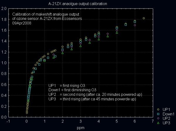
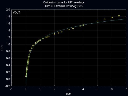
- ozone:
-
·
A-21ZX from
ECO-Sensors (http://www.ecosensors.com/a21zx.html
)
-
·
available
from meteoLCD
-
·
air will be
led to the sensor through a tubing system with the help of a LEGO-made
air-pump
-
·
on the way
to the sensor the air will be possibly heated up to
the ambient temperature of the inner box
-
·
the A-21ZX
has no available output port; it therefore is hacked to the analog sensor
line that enters the internal microcontroller
-
·
output
voltage 0..2V
-
·
the sensor
has an own battery system that will be fully charged at start; however, to
maintain the voltage, the device is also connected to the main supply
-
·
if being
charged, the sensor needs about 40mA at 12V
- air-pressure:
-
·
SCX15AN
from Sensor Technics (http://www.sensortechnics.com/
)
-
·
available
from meteoLCD
-
·
absolute
pressure sensor that covers the range from 0..1200hP
-
·
will be
manually calibrated before implementation
-
·
sensor is
extended with an OpAmp circuit to have an output voltage of 0..2V
-
·
sensor
consumes about 15mA at 12V
- air-temperature
(outside) :
-
·
PT100
-
·
available
from meteoLCD
-
·
extended
with an OpAmp circuit that acts as a constant current source
-
·
output
voltage 0..2V
-
·
sensor
consumes 12mA at 12V
- temperature
(inside) :
-
·
standard LEGO
temperature sensor
- back
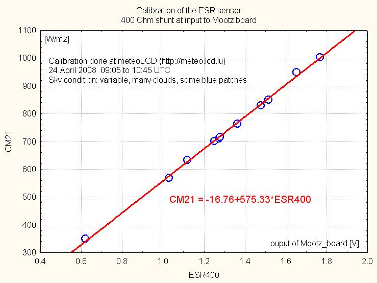
scattered light sensor :
-
·
Vintage ESR
SI-diode sensor from Delta-T (http://www.delta-t.co.uk)
-
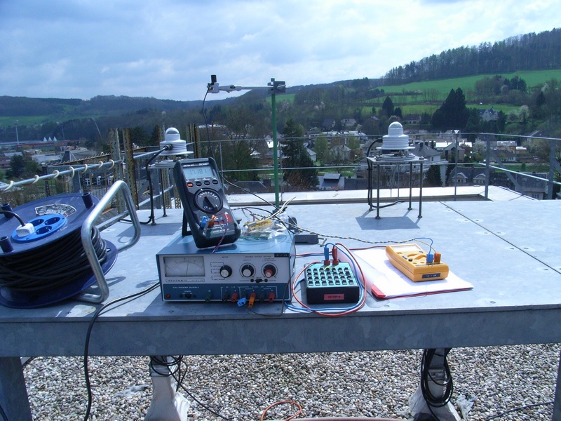
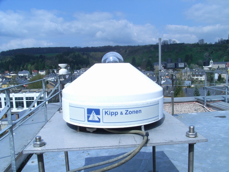
·
available
from meteoLCD, calibrated against a CM-21 pyranometer from Kipp & Zonen
-
·
some more
detailed information is still missing
- optionally
: autonomous Geiger-counter datalogger
-
·
Gamma-Scout (http://www.gamma-scout.com/
)
-
·
fully
autonomous from the rest of the system
-
·
measures
the dose rate in microSv/h or counts in Bq; measures beta + gamma
- operation:
a single switch will start all sensors and the logging/command
procedures of the NXT computer. It is assumed that the payload
(of which LUXPAK is one component) will be brought back safe by a
parachute, so the equipment should survive a rough landing
|
|
|
2008/04/10
|
|
|
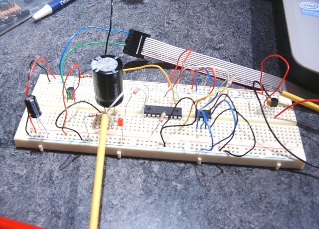
2008/04/11
(little error on
th picture: 16F819 instead of the indicated 16F84)
-
The PIC is programmed to wake up
the card in SPI mode (send a series of 0xFF with /CS=HIGH) and send a
command 0x40 0x00 0x00 0x95 that should return a result 0x1. (If the
transaction succeeds, the LED will flash slowly. In the other case, it will
blink quickly. Here the Ultimate
ROBOLAB for PICs program: ATTENTION
(added April 12th): two vis have been inverted !!!
-
Obviously there is a mistake in
the first equation of the 7-bit cyclic redundancy check (CRC7). It should be
written: G(x)=x7+x3+1.
-
But, using the formulas, it is
impossible to obtain the correct CRC. It seems that SD producers don't
publish everything openly.
-
Example: CMD0 (GO_IDLE_STATE -
reset the SD Card) : byte1 = 0x40; bytes 2-5 = 0; byte 6 = 0x95
-
G(x)=137, x=2
-
M(x)=64*2564=274877906944
-
CRC=(274877906944 * 128) mod
137 = 7
-
and byte 6 would equal
7*2+1=0xF
After some calculations, we
found that there is only one way to obtain the correct 6th byte:
-
CRC[6..0] = Remainder
[(M(x)*(x7)2)/G(x)], so the augmentation (that's
the official name for this multiplication in this CRC calculation) must
be done differently than indicated in the manual.
-
with this formula we get:
CRC=(274877906944 * 1282) mod 137 = 4503599627370496 mod 137
= 74
-
and byte 6 equals
74*2+1=0x95
-
Fortunately the manual tells us
that the CRC byte only is required for CMD0. The checking is disabled
otherwise in SPI-mode.
|
|
|
2008/04/12
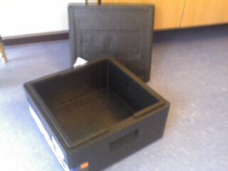
-
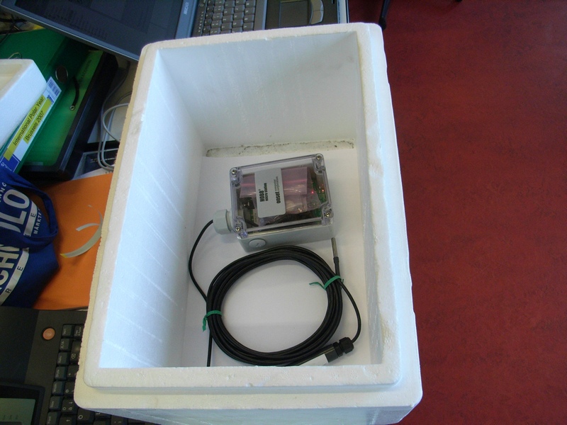
Yannick Zanella, our cook,
phoned a lot in order to get one of those freezing boxes made of hard
polystyrene. Thanks, Yannick!
-
We will have to cut down that box, because he was only able to find 40x40xN cm3 (N=16.5; 24; 40) The one
we now have is 40x40x24. Cutting it will make it 40x20x24.
|
|
|
2008/04/14
-
Jean Mootz has joined the team.
Cool ! A few greatful
words about this most exceptional person have been expressed by ETH
Professor Dr. François Diederich, ... the very best of the long list of
scientists, engineers and pedagogues who have enjoyed Jean Mootz in class.
|
|
|
2008/04/15
-
Francis will investigate the
loss of temperature with a 11 grad high school class (IIIe), while treating the theme of the
thermical conduction. We will abandon the idea of the thermic insulating
wrapping. The polystyrene case normally will be sufficient.
-
Francis also has weighted two
sensors:
-
Mass Gamma-Scout = 150g
-
Mass O3 sensor =
134g
|
|
|
2008/04/16
-
Eric Wang says:
-
That we can expect the
balloon to ascend at about 1000-1200 feet per minute. It's expected to reach between 85000 to 105000 feet.
-
The altitude is based on GPS
and is data logged for the entire mission automatically once per second
by an onboard system and its also recoded by the ground station once
every 30 seconds.
-
The full mission data from
all the payloads will be made available to everyone after the mission.
|
|
|
2008/04/17
-
We will abandon the SD Card
idea, because by no means we were able to write or read data to the card. We
guess that there is essential information that is not available on the web
about data token, error handling and so on. Or we are doing something
completely wrong. But, we didn't find the bug. :-(
-
Instead Claude is playing with a
serial I2C EEPROM that can be connected to a PIC much more easily. We intend
to use the 16F88 that has an SSP-module. Unfortunately this is not
sufficient to assure hardware master I2C (an MSSP would be required.) But
it's rather an easy thing to set up a bit-banged protocol.
-
We will follow Sprut's
idea in order to have 2 "open-drain" driver-lines. He suggests
using 4 pins, separating output and input signals through diodes. This is
quite an generous use of rare pins, but the advantege is that the ports must
not constantly toggle between output and input functions, and that much
higher currents can be sunk.
-
The diodes also give the
possibility to verify the presence of the acknowledgment bit very easily.
-
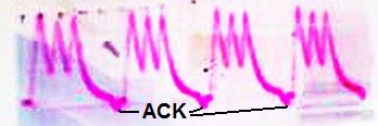
Using his code inside an
Ultimate Robolab for PICs program with a test 24C08B EEPROM, we are able to
obtain the acknowledgment (ACK) pulse from the EEPROM, when sending the
control byte b'10100000'. We also are able to write and read a byte to the EEPROM.
-
The following pictures show
oscillograph pictures of repeated control byte sending and the RX of the ACK
bit (pulling down the SDA line)
diode blocked SDA signal

SDA signal with ACK
-
The start condition can be
recognized (HIGH to LOW transistion), then the bits b'10100000', the ACK
bit and the final stop-bit.
-
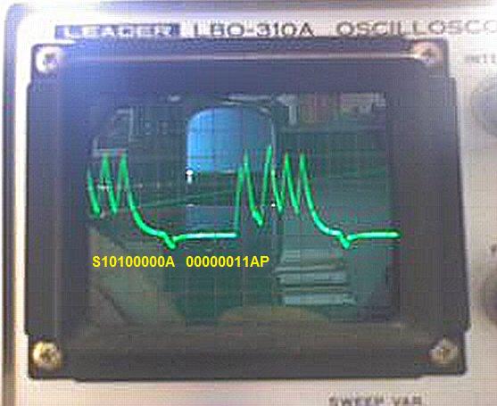
Here the sending of the
control byte and the data address 0x03, followed by the stop bit:
-
Note that Sprut has masked
the wait for ACK as comment in the i2c_tx routine. If the ACK does not
appear, the program could hang up here. Thus, a timeout function needs
to be added either through the watchdog timer, another timer or a simple
counter.
-
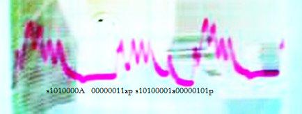
The following shot shows the
sequence of reading the value 0x05 (b'00000101') from memory address
0x03 (b'00000011'). The reading sequence is:
-
send start bit
-
send write-control-byte
0xA0 (b'10100000')
-
wait for ACK
-
send address 0x03 (NOTE
that 24C08B only needs one address byte, the page address is given
by the 3 lower bits of the control byte)
-
wait for ACK
-
send stop bit
-
send start bit
-
send read-control-byte
0xA1 (b'10100001')
-
wait for ACK
-
read byte (no master
ACK)
-
send stop bit
|
|
|
2008/04/18
-
First tests with the air pump:
-
we want to use the LEGO red
micromotor (Part. 2986) that according to Philo
has a stalled torque of 1.6N.cm, a stalled current of 80mA, no-load
current 6mA, produces at 9V 16rpm, with 21mW mechanical power at an
efficiency of 16% (current 40mA). This
motor has a few advantages for this purpose:
-
Using a single piston, this
motor is able to move about 5cm^3/minute, which is sufficient for the
O3-sensor.
-
The piston system needs to
be placed inside of an air-proof box that has an inlet and an outlet.
-
Although Sprut's
I2C code succesfully sends bytes to the
24C08B EEPROM, and also receives the correct RX-message, the I2C_RX routine
(RdI2cW-subroutine) has a serious bug, that he probably does not notice,
because he is using 16F628 Schmitt-Trigger inputs. Since we are going to
work with the 16F88 that only has TTL inputs, the bug badly affects the RX.
In fact, with the original code it is not possible to extract the byte from
the signal (the code between ;++++++ is the RdI2cW-code):
-
The routine reads the
data-bit BEFORE the clock goes HIGH, which is wrong according to the
I2C specifications. The data is only valid during the clock HIGH
state. We must change the code to:
-
;+++++++++++++++++++++++++++++++++++
clrf buf
movlw 8
movwf cntbt
bsf SDAo ;failsave
RdI2cW1
nop
bsf SCL ; Takt high
RdI2cW2
btfss SCLi
goto RdI2cW2
clrc
btfsc SDAi
setc
rlf buf,f
bcf SCL ; Takt low
decfsz cntbt,f ; 8 Bits drinn?
goto RdI2cW1 ; nein
movfw buf ; ja fertig
;+++++++++++++++++++++++++++++++++++
|
|
|
2008/04/19
-
We definitely abandoned Sprut's
code. Although TX works without fail, RX produces many data errors. One
issue could be the capacitance of the diodes.
-
==> we switched to Microchip's
source code. They are using the meanwhile illegal instruction TRIS, that
we must replace with a sequence:
-
The Microchip author sets the
dataline HIGH by switching the pin to input mode. We changed the code in
that way that in the beginning of the TX routine, the SDA-line is set to
output. Then the bits are sent by pulling the pin high or low. When reading
the ACK-bit, the pin is changed to input. ATTENTION: switching to output
internally sets the pin in LOW state, which produces bad readings on the
device side. Therefore we first set the pin HIGH, as if it already was
configured as output. Then we toggle the mode to input, and the pin remains
HIGH:
-
We also add a few NOPs to
improve the timing
-
The software now produces an
error (i2c_error=1), if the ACK is not received from the device.
-
Download
URP (ULTIMATE ROBOLAB for PICs) code for sending (test_TX.vi) and
reading (test_RX.vi)
-
In this library you also will
find test_i2c_loop_uart.vi (see below), that first writes 255 bytes to the
EEPROM, then reads them out and sends them over the serial UART channel.
(Note that the 16F88 is not pin compatible with the 16F628 for the UART.)
-
This confirms that we are
able to use I2C, UART and ADC without fail on the 16F88.
-
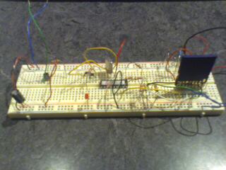
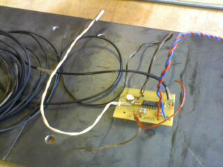
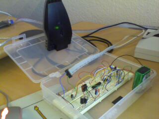
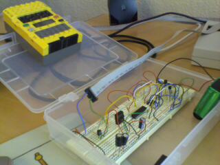
Here the breadboard for the
capacitor experiment.
-
Now we started playing with
the pressure sensor. Connecting the sensor-board (sensor plus op-amp
circuit) to the experimental logger with a LEGO piston and tubing that
allows some controlled pressure steps. The voltage is obtained by adding
a 10k pull-up resistor to the PIC input port and connecting the
sensor-board output to the logger ground and the sensor-board ground via
100k to the PIC. The sensor negative voltage (compared to the PIC-board)
REDUCES the PIC ADC voltage, as the pressure increases. Note that we
added a 1k resistor between the 10k/100k bridge and the PIC input in
order to prevent accidental high current.
 |
Francis suggests a very
simple and astute solution for the air
transport. The deduced necessary heating power is described in the
Excel-sheet. The calculations
estimate the heating in function of the flight altitude: |
|
|
|
2008/04/21
|
|
|
2008/04/22
-
Now the datalogger prototype (let's call it
PICLOG) is able to send from RAM, receive, store to RAM and
verify the integrity of RCX infrared packets.
-
Packet form :
-
header : 55 FF 00
-
opcode : 1 byte + complement
byte
-
parameters : N
bytes + N complements
-
checksum : 1 byte +
complement
Note that the RCX needs the
9th parity bit (odd), while the PC-tower doesn't require it. -
Maximum packet size : N
= 94 bytes
-
Before sending a packet,
software must add the checksum
-
Packets are stored in RAM (or
later in EEPROM) in the form:
-
opcode : 1 byte
-
parameters : N
bytes
-
checksum : 1 byte
-
(The reason for also
saving the checksum is a small gain of speed and memory. Later the
PC will send the RCX firmware to PICLOG through the normal RCX
download procedure. Thus the packets will already contain the
correct checksum. The firmware packets also will contain the block
data, the block checksums and the firmware, which must not be
calculated again. Note however that firmware packets will not have
the normal 200 payload bytes size)
-
The sending is done through a
back-to-back machine. The 16F88 UART generates an interrupt, if the hardware
buffer has been emptied. The interrupt service routine then sends the next
byte to the hardware buffer until the last byte has been sent. This
mechanism does not generate any transmisison error, because the next byte is
only moved from RAM to the hardware buffer, if the buffer is free.
-
However it might happen that the
RX interrupt handling is slower than the arriving byte rate due to other
interrupt handling for example. This would produce a RX hardware buffer
overrun. The infrared channel also could capture bad packets (missing bytes,
for instance). This will be detected by the packet integrity tests.
-
Note that software must clear th
error states
-
If a VALID packet has been
received and stored into RAM, the UART module will no longer store any byte
to RAM. TX will also be prohibited. The software has to react to the packet
and clear the VALID state.
-
The UART system only works in
half duplex, because RX and TX use the same infrared channel.
-
The UART software module works
as a state machine :
-
TODO: Note that the state
machine could be blocked in RX-state, if the transmission was disrupted.
In that case, a certain number of bytes would be necessary to generate
an error state. Therefore the main software should verify, if the
program remains in RX-state too long.
-
Now PICLOG will be
programmed to correctly receive and store an RCX firmware to EEPROM.
-
Later, this will only be
allowed, if a jumper is set, in order to prevent accidental erase of
the RCX firmware
-
The following step will be
the transmission of the firmware from EEPROM to the RCX.
|
|
|
2008/04/23
-
Today's discussion with Francis,
Jean-Claude Krack, who also joined the company and Claude. Main discussion
points:
-
Isolating box
-
The one shown above
definitely is too big. Either we cut it with a hot wire and glue it
or we try to find a better sized one
-
Francis made a few tests
in the freezer with a soft polystyrene box about 40x20x20cm; wall :
25mm:
-
Jean-Claude carries
along another model, white coloured 40x26x26cm, which might do the
job; wall 3cm. He also proposes to ask his liquid air provider.
Thanks Jean-Claude.
Heating:
-
Isolation for the
electronics and tubing will be done by non-inflammable isolating
material
-
Batteries: Francis is
looking for the best possible model.
-
Jean Mootz already finished
the constant current supply for the PTR100 with ap-amps also for the
light sensor. Thanks a lot.
-
PICLOG now is able to talk to an
RCX or a PC through the LEGO tower. We also can "download" a LEGO
RCX firmware to PICLOG. The firmware isn't stored to EEPROM yet, but all the
bytes are well received and the replies are sent correctly. (The PICLOG does
not understand the unlock command, which is not necessary anyway. This will
cause an error-message. (We will add this reply only, if there remains
enough memory space on the PIC.) There are only 2 things that must be
changed in the PC downloader program:
-
Instead of using the
standard 200 bytes payload for one 0x45 packet, we only allow 89
(=96-7). The 16F88 RX buffer is limited to 96 bytes by our software
(bank2). The downloader adds 7 control bytes.
-
The last packet must be
filled with zeros to have the same data-size
|
|
|
2008/04/24
-
Francis weighted some more
parts:
-
He must add a terminating 10k
resistor to the light sensor
-
Francis will repeat the cooling
test in the freezer for Jean-Claude's box. It seems to be impossible to
thermically stabilize an empty container. He therefore adds a bottle of
200ml water (c=4185) corresponding to about 800g of material with c
estimated between 800 and 1200)
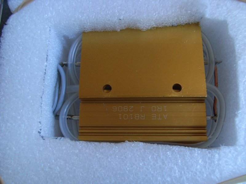
-
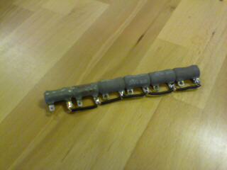
The resistor net now has 3
parallel blocks of two serial resistors. The temperature reaches 75° at
600mA current. (The RCX will not be able to provide this current directly,
so one port will only be used to switch on an off a power transistor like
the 2N3055.
-
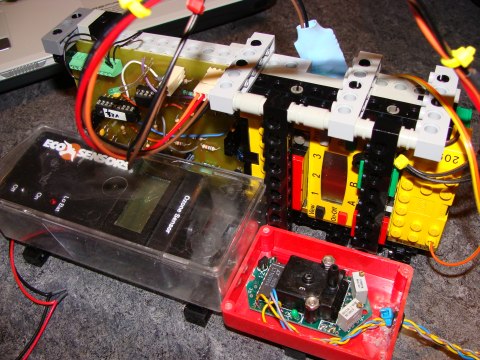
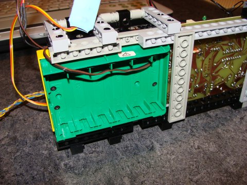
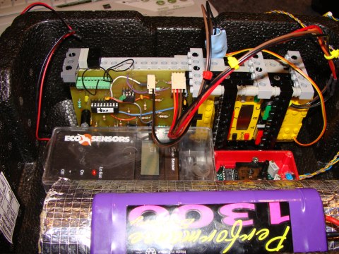
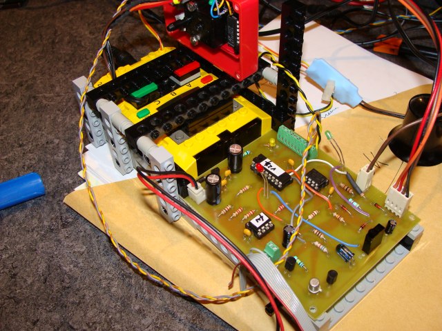
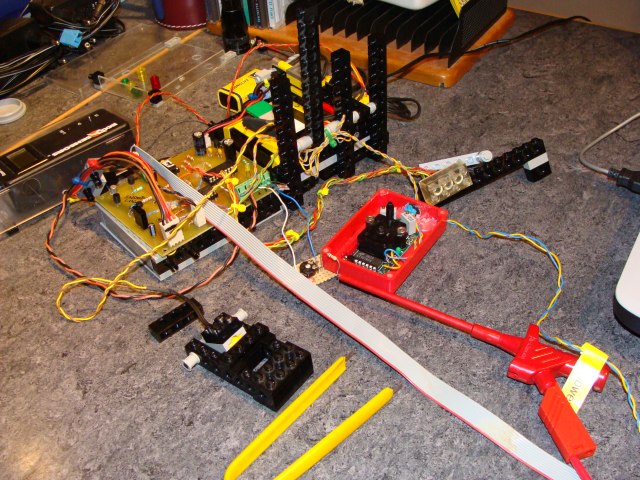
Here a few shots of the selected
and realized devices:
|
|
|
2008/04/27
-
Now PICLOG is able to receive an
RCX firmware, store it in EEPROM memory and correctly answer all the replies
to the ROBOLAB firmware download program. The only major change had to be
done in the downloader. Instead of sending all the firmware packets to the
internal serial sub.vi, we send them one by one, adding a generous pause
between each block to give PICLOG the time to store the bytes in EEPROM. As
already said, the block-size is limited to 89 payload bytes (totally 96
bytes) and the last packet is filled up with zeros to have the same size.
-
Here a screen-shot of the PICLOG
replies that have been sniffed from the serial communication. The last
firmware block has been correctly received and is accepted with a B2 00
reply (0xB2 is the complement of 0xAD - the toggle bit is set in this
packet). Then PICLOG replies with 5A "Just a bit off the block!"
to the UnlockFirmware command 0xA5 (toggle bit cleared.) Note that the rest
of the bytes are part of a debugging message that uploaded the contents of
the UART RX buffer. Parts of the previous packet has been overwritten with
the very last received packet A5 LEGO... and you can read the firmware
terminating code "Do you byte, when I knock?". Also note the
couples of yellow framed bytes which are dummy bytes sent by PICLOG software
to the internal UART TX buffer, in order to keep the IR-carrier on
oscillating during the transmission of the infrared packets. These dummy
bytes are NOT sent by infrared, because at the moment the 16F88 UART module
would empty its hardware TX buffers, the carrier is already shut off.
- Uploaded our proposal document for
participation in H.A.L.E.
|
|
|
2008/04/28
-
Now PICLOG also is able to
correctly send an RCX firmware that previously has been stored into EEPROM
from PC via LEGO tower.
-
Here a few shots: 1. download to
PIC from LEGO tower 2. download to RCX from
PIC 3. RCX in download mode
-
Unfortunately the PIC
programs to receive, store and send RCX firmwares occupy almost the
whole PIC memory.
-
==> we separate the
projects into 3 devices :
-
an EEPROMer device that
will allow to fill EEPROMs with RCX firmwares using the LEGO tower
-
an RCX bootloader that
will switch on the RCX, detect the presence of the firmware and if
not deteceted, send it to the RCX
-
PICLOG that will do all
the datalogging while storing sensor data and received data from the
RCX
-
The RCX will be the central
unit:
-
we will use the specially
prepared RCX with the small phototransistor
able to be switch on
and off by external devices
-
the bootloader will
measure the sensor port voltage. If the voltage is zero, the
bootloader (we will call it SNOOP_LOAD)
will shortly and brightly flash a LED. The RCX is switched on.
SNOOP_LOAD recognizes this through the presence of a voltage.
-
If the firmware (we'll
call it HALE_fw)
is there, it will switch on RCX PORT C that serves as the power
supply for PICLOG. SNOOP_LOAD also checks this voltage. If it is
present, then SNOOP_LOAD will go into sleep mode. (It regularly will
wake up to control the state.)
-
If the firmware is not
detected, then the download process is started.
|
|
|
2008/05/01
-
First we thought that we could
do the datalogging and bootloading in one device. Then we found that the
bootloader needed two different devices: the bootloader (called so far
SNOOP_LOAD) and the EEPROMer. And PICLOG would represent a third device.
-
But now we are certain,...
because everything correctly works, that we definetely need only 2
electronics:
|
|
- The microcontroller program of
 is easy to describe (see above). It needs to reply correctly to the
following LEGO RCX opcodes:
is easy to describe (see above). It needs to reply correctly to the
following LEGO RCX opcodes:
- 0x10 (PING)
- 0x65 (RESET)
- 0x75 (START FIRMWARE DOWNLOAD, also get
the firmware checksum -SNOOP_BURN needs to store this to EEPROM address
0x7FFE (little endian) )
- 0x45 (SEND FIRMWARE BLOCK): firmware
blocks have a block number starting with 1. The last block has number 0.
From the block number the SNOOP_BURN
calculates the correct EEPROM
address for the block. Each block has 96 bytes, corresponding to the
maximum buffer size in one bank of the PIC 16F88. The block data is
stored with the opcode and the checksum, but without the header and the
complements. (This makes the sending procedure for SNOOP_LOG
slightly easier.)
- 0xA5 (ULNOCK FIRMWARE): SNOOP_BURN
does not check the integrity of the
firmware. But, since SNOOP_BURN
verifies the transmission of every
block, we are certain that it received the firmware without fail.
- The program does not abort the download,
if any error occurred. (This does never happen, since the only error
that could compromise the procedure is the I2C ACK missing error. We are
certain about the I2C channel, so why should something happen.). The
data security comes from the ROBOLAB firmware download program, which
surveys the integrity of the replies during the download. If a packet is
not received, because an UART error occurred, the PC software simply
resends the packet.
- The only restrictions to normal the RCX
firmware receive procedure are in relationship with the boot_loader:
- 0x45 packets have the form:
| 0x45 |
block_ID_LO |
block_ID_HI |
N_LO |
N_HI |
data[0] |
... |
data[N-1] |
block-checksum |
checksum |
| 1t |
2nd |
3d
(=0) |
4th
(=96) |
5th
(=0) |
data[0] |
|
data[88] |
6th |
7th |
- ==> Each block can transport 89 payload
bytes and has 7 packet information bytes.
- The PC download software in ROBOLAB is changed
from the ULTIMATE ROBOLAB "Download_s_record.vi". the two major
changes are:
- The last remaining packet is filled up
with dummy zeros in order to have 89 payload bytes
- Each block is individually sent to SNOOP_BURN,
because the EEPROM storing generates a 1 second delay to the normal
reply.
|
|
|
-
The bootloader part executes
the flowchart below: (a pause is added at the end to give the RCX the
chance to run the firmware)
-
Firmware
checksum is NOT computed by the bootloader, but must have been stored by
SNOOP_BURN at EEPROM address 0x7FFE little endian)
-
EEPROM hardware address is 0
! It is not possible to accidentally overwrite the firmware EEPROM,
because the hardware Write Protection (WP) pin is set.
-
The only EEPROM read error
might be a missing ACK. This did never happen in the tests. Our I2C
bit-banged master runs without fail. We could force this error, if the
EEPROM enable pins are bad wired or either the clock or the data lines
were unconnected.
-
RCX firmwares never exceed
20kB. If zero block_ID never appears, which only is the case, if no
valid firmware was present on the EEPROM, the program needs to detect
this.
-
From the RCX virus
experiment, we know that firmware download works very reliably at
2400baud. Download rarely fails. Due to an RCX firmware bug, any block
sending fail could hang up the firmware download, and the process has to
be manually stopped. (This happens with any firmware downloader). But,
if we don't check the RCX reply and have the RCX verify the firmware
integrity after download through the firmware checksum, then there are
many chances that the firmware has been correctly stored, even if a
packet integrity issue happened during transmission. If the RCX does not
accept the firmware, it sends an acoustical signal and resets its
internal state. SNOOP_LOG
can restart transmitting the firmware.
-
In the dark of LUXPAK
interior the chances of IR disturbances are zero. Thus, we can expect
that we have a 100% reliable IR-connection between SNOOP_LOG
and the RCX.
-
If for any reason the
firmware download could not work, there are two precautions:
-
The RCX firmware will be
pre-installed on the RCX. We need to calculate the energy loss
during a 2 weeks travel from Luxembourg to the launch place. We know
the RCX consumes 34microA in software stand-by mode. The bootloading
would then only be necessary, if the firmware had been accidently
lost. (Due to energy economy this measure could be impossible ==>
we have to think here.)
-
The RCX firmware
-delivered as a .srec file- can be downloaded to the RCX through
ROBOLAB manually. (Eric, this could be your job. If within 10
minutes the system does not work, this would be the option.)
|
|
- The datalogging function of SNOOP_LOG
works according to the following conventions:
- The RCX is the intiator of any
datalogging
- The RCX firmware regularly sends a
series of LASM SETV (opcode 0x14 (variable number, source,
value_LO, value_HI) commands
- variable 0 .. 4 SNOOP_LOG
reads its analog channels 0..4 (note that channel 3 is the 2V
reference voltage) and stores the values in RAM
- variables 5 .. 31 SNOOP_LOG
stores value_LO, value_HI that it received from the RCX into RAM
at the address given through the variable number
- If a whole record has been stored, the
RCX sends out a message 0xF7 (1), which tells SNOOP_LOG
to transfer the RAM to the next EEPROM slot.
- EEPROM hardware address is 1
- The RCX will run a clock that will
provide a time stamp for each record.
- If the EEPROM reaches the end of
its capacity, no other data will be stored and the program
generates a "memory full" error. The last 2 bytes are
lost anyway, but the raw data analyzing software should ignore
the very last record.
- 0xF7 (2) may be sent to SNOOP_LOG
later in order to extract the data from EEPROM. SNOOP_LOG
will then stream the raw data through the serial channel to the PC
(RS232). The IR-carrier will be shut off, and the data will not be
sent on the IR-channel. PC software should extract the records from
the raw data.
- 0xF7 (dec57=0x39) resets the EEPROM
HIMEM pointing to the next free address on EEPROM. Note that
switching SNOOP_LOG
off will not affect the EEPROM pointer. (The data pointer is
localized on the PIC 16F88 internal EEPROM address 0x0 (little
endian).
- The RCX does not know, whether the
current data received from SNOOP_LOG
belongs to the same data record. (It was not possible to add any
reply protocol or record integrity checking, because the PIC 16F88
run out of program memory.) But, if we make sure that enough time is
paused between the RCX data sending, then SNOOP_LOG
will have had the time to clear any UART error, which could be the
only error source here.
|
|
|
|
|
|
2008/05/05
-
I2C ACK missing (should
never happen)
-
UART RX error (overrun,
header, complement or checksum error -rarely happens, especially in
the dark of LUXPAK's box)
-
Block address error -
attempt to write a firmware block beyond the allowed RCX limits
(24000 bytes) -should not happen
-
Data-logger full -should
not happen
-
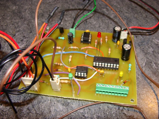
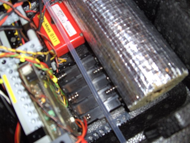
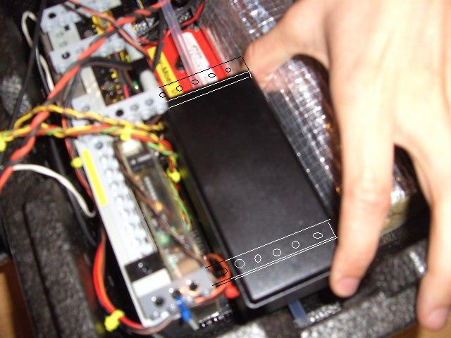
PHOTOS:
-
Note that yellow LED D3
and the small signal LED D9 replace a 2V Zener diode of an earlier
version (that is no longer available here in order to avoid version
conflicts.
-
The long green analog
channel connector has the following order.(Note that if one analog
input should be used unplugged, it should be grounded through a 100k
resistor in order to avoid floating input effects. Alos note that
the 2V reference voltage is high impedance, it cannot be used as a
power supply.)
| 1 |
2 |
3 |
4 |
5 |
6 |
7 |
8 |
9 |
10 |
| GND |
AN0 |
GND |
AN1 |
GND |
AN2 |
GND |
2V Ref. |
GND |
AN4 |
-
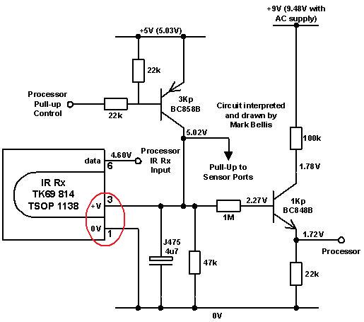
In order do save one RCX
input line, we solder a wire to the +V pin and the 0V pin of the IR
receiver and we add an external 100nF decoupling capacitor. The +V pin
always has 0V, if the RCX is switched off and +5V, if switched on. We
therefore may use the pin as a hardware indicator of the RCX basic
state. This voltage is not affected through IR-traffic. (cf. Mark
Bellis' circuit description on the next picture.)
-
The flowchart from above
changes to:
|
|
|
2008/05/06
-
The first long-time test of
our SNOOP_LOG prototype reveals a few things:
-
Switch on RCX never
fails
-
However, passing into
boot-mode sometimes fails. The reason is that PIC16F88 pin RB7
sometimes reads a TTL level HIGH although the RCX port C has not
been switched on. When running the executive, the RCX output ports
seem to be in float mode. At RB7 we measure 1V, which should produce
TTL LOW. Probably there are some spurious peaks, because through the
RCX float mode, the RB7 input encounters high impedance on the RCX
counter-part. Therefore
we add a 10k resistor in parallel to Zener diode D1.
-
The voltage between GND
and -V of the RCX output is 0.3V. We therefore reduce R8 from 33k to
100R.
-
If the RCX is switched
on before SNOOP_LOG (which should only happen during tests), RB6
reacts as an low impedance output with level LOW and a rather high
current is shortly drawn until the SNOOP_LOG power-up. We
therefore add a 10k resitor in series with blocking diode D5 in
order to protect both the RCX and PIC16F88 from damage.
-
Firmware download to the
RCX from SNOOP_LOG never fails.
-
In datalog mode, we
sometimes get an UART error message, if two 0xF7 (1) messages
succeed to rapidly. The reason is that this message causes SNOOP_LOG
to store the data on EEPROM. In the actual version (_v23) the record
length is 16 bytes. The EEPROM writing needs 8ms per byte (we added
3ms to the prescribed 5ms in order to avoid any write error.). Since
the data pointer also is saved in EEPROM, two write cycles must be
added. The RCX absolutely needs to respect a generous delay between
two 0xF7 (1) messages to give SNOOP_LOG the time to reset the UART
in RX-mode. Note that after a 0xF7 (2) message SNOOP_LOG is unable
to receive for the duration of the data output stream.
-
What do we measure with
SNOOP_LOG:
-
SNOOP_LOG analog inputs
AN0/AN1/AN2/AN4. We do not need to read the reference voltage AN3,
because the raw value always is 0x3FF. But it could be an excellent
bad record indicator, in the case of a value that would differ from
that value. ==> (5 words)
-
RCX values
-
time since start in
seconds (1 word)
-
Sensor 1 & 2 (2
words) (for sensor 3 see below)
-
Output state A & B
(2 words)
-
battery level (1
word)
-
termination word
(0x0D 0x0A = end of line) to help the PC software to better analyze the raw
data. (1 word) (If ever there was a spurious EEPROM write error, we'd
detect it in a single record, without affecting the whole
dataset.)
-
Total : 12 * 2 = 24
bytes
-
What timing can we expect:
-
The datalogging time is
estimated to 2 hours ==> 32766 bytes /24/ 7200 ~= 0.20
records / 1s ~= 1 record/5s maximal EEPROM sampling rate
-
Each single sampling in RAM
will be executed after an RCX 0x14 (p1, p2, p3, p4) command. The
transmission of this command (15 bytes sent) needs 15*12/2400 =0.075 seconds. Remember that there are 8 bits + stop bit + start
bit + parity bit = 11bits per byte. Add a small pause necessary to
rearm the UART, let's say another 65ms... and you get a maximal
RAM sampling rate of 7word/s
-
In order to keep the
communication as much as possible error-free, we increase the
timing, since there is no feed-back from SNOOP_LOG to the RCX : send
0x14 command every 0.5sec. After having sent the 12 successive 0x14
commands, send the 0xF1 (1) command telling SNOOP_LOG to transfer the
data to the EEPROM. Wait 2 seconds after this command : realistic
error-free record sampling rate : 1/8 = 0.125Hz = 7.5rec/min.
We expect an ascension speed of
5m/s, thus we sample once every 37.5m, which absolutely is
acceptable.
-
==> SNOOP_LOG
program must be changed to accept 24 bytes instead of actual 16 !!!
|
|
|
2008/05/08
|
|
- Conclusions:
- We need the lightest possible NiMH battery
pack !!! ==>
first estimate the needed energy
- NiMH seem to have the best
characteristics for this purpose although they present the serious
issue of self-discharge
- No inner box will be used
|
|
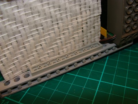
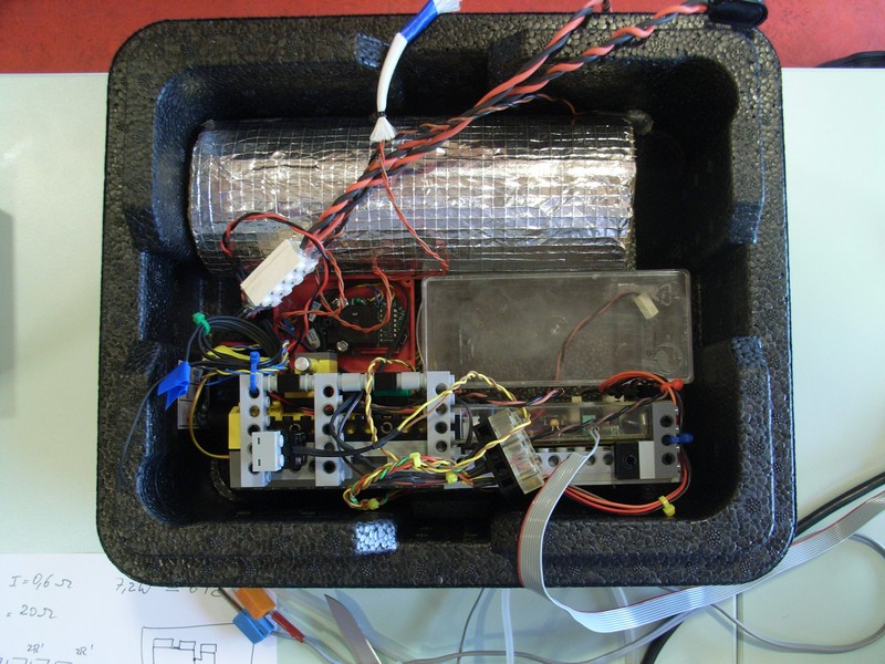
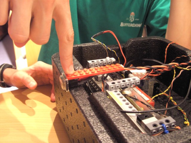
- The electronics need to be fixed to the
inner box.
- The glass-wool isolation will be glued
to the box bottom
- O3 sensor must be placed inside of a
small box that also will be glued to one wall
- For the battery, RCX and SNOOP_LOG,
Erik and Laurent suggest:
- Battery pack fixed with rubber
belt (we use an old pack on the next picture that was
disponible)
- SNOOP_LOG PCboard clamped between
LEGO brick and plates.
- The pressure sensor should be
fixed to the wall. (Not sure about this idea, because of the
thermical conduction
- Alessio proposes to use a solar panel
to compensate the loss of electric power in the NiMH accus during
the transportation from Luxembourg to Nevada
|
|
- Questions about the heating:
- How much heating will we need in the
tubing? (see above)
- What is changing, if we use a larger
tube diameter?
- How fast does the polystyrene box cool
down?
- If we add a heater inside of the box,
how can w eprovide thermical conduction to the electronic devices?
- convection at lower altitudes and
high air pressure
- radiation at higher altitudes and
low air pressure (we know that vaccuum is an excellent thermical
isolator, but our heaters won't radiate at low temperatures!!!)
- Suggestions:
- the RCX is powered with DC
through the AC adapter plug. If the RCX consumes 100mA, this
will produce a heating in the RCX rectifier bridge and
voltage-regulator of (12-9)*0.1 = 0.3W. These parts are
soldered on the RCX PCboard and thus thermical conduction is
assured
- SNOOP_LOG has low power
consumption : ?????
- Mootz_board: same issue
- Pressure sensor : idem
- battery pack : NiMH work best
at high temperature. If we have enough current, the inner
resistance will produce enough heat: ==> no problem
- O3-sensor receives the heated
air : ==> no problem
- ==> Have the RCX
directly supply the heating resistors (the higher
current will increase the heat in the RCX electronics)
- distribute box resistors:
glue them to SNOOP_LOG and Mootz_board PCboards.
- The box has a total surface of
(0.3x0.25x2)+(0.3x0.153x2)+(0.25x0.153x2)=0.3183m^2
- Filled with about 1kg of different
materials, we obtain the following curve for the box in a freezer at
-18° (ROBOLAB Investigator, RCX, LEGO temperature sensor):
|
|
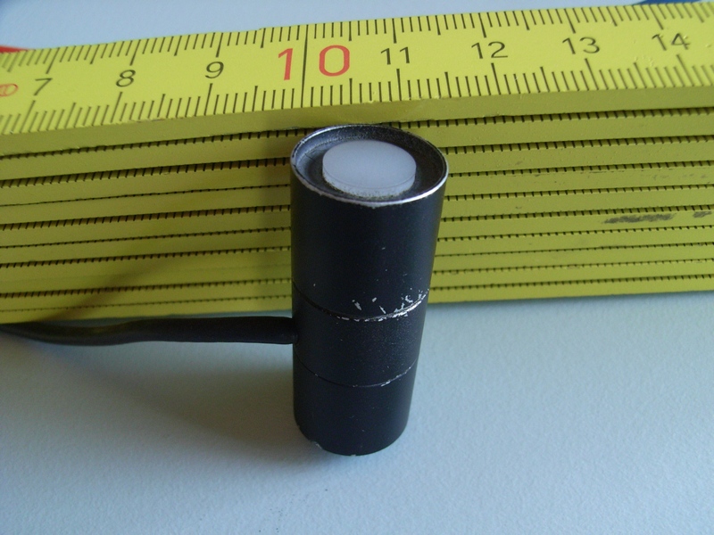
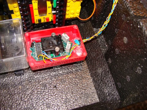
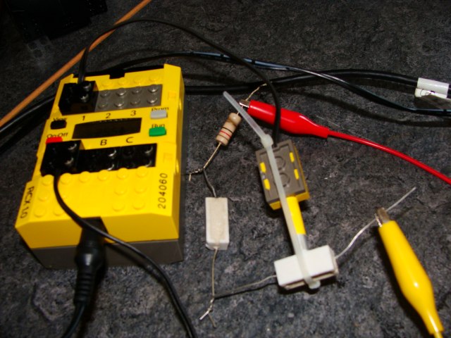
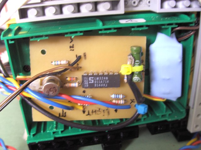
- A picture of the optocoupler between
SNOOP_LOG and the RCX (On/Off) button. The LED side is connected to
SNOOP_LOG with a 220Ohm resistor. The photo-transistor side is wired to
the On/Off button as shown in http://www.convict.lu/htm/rob/mars_IV.htm
. No resistor is being used in this circuit, because the RCX already has
a pull-up resistor.
|
|
|
2008/05/09
-
We are not certain yet, how
LUXPAK should be connected to the balloon. One possibility is a steel
string that might be tied through the box. If this was the case, Laurent
and Eric's design has to be changed a bit:
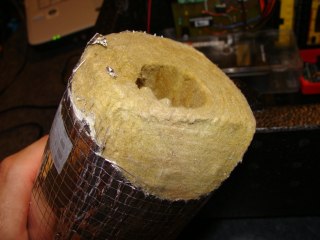
-
The isolation cylinder that
will receive the tubing with the resistors must be cut to 45° in order
to fit to the bottom of the box.
-
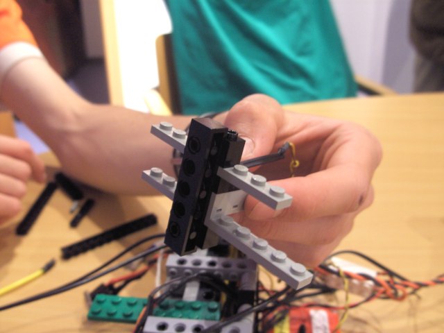
Practically the LEGO beams
exactly have the size of the box inner height 95mm ==> fixing the
whole LUXPAK device block to the box is very easy.
|
|
- Important
transformation:
- Disposed as shown above, we loose 27%
of the data records due to UART errors.
- After a few tests, we found out that
SNOOP_board's IR-receiver is placed too close to the RCX LEDs
- ==> we rotate both the TSOP1738 and
the IR-LED on the PCboard by 180° ;-( This is prototyping !!!!
-
Now SNOOP_LOG and RCX's
IR-devices are distant by 10cm, and the communication is perfect at
100% again. (We will have long-term tests soon.) Anyway, LEGO
recommends 10cm distance between the LEGO tower and the RCX. The
reason probably is that the high-gain TSOP IR-decoder is too
sensitive.
|
|
|
2008/05/09
-
Francis is working on an
overall report concerning the heating problem. He is studying the
subject from a more theoretical point of view and verifies his
calculations through experiments.
-
Battery options:
-
We tested the SNOOP_LOG /
RCX combination under the following conditions:
-
40 data records (the
first and the last record are lost - the first one, because the PIC
ADC needs a few samplings, before it is able to do correct readings;
why we loose the last one: no cue! SNOOP_LOG did not show any UART
error, nor did we see any I2C error... bug somewhere?)
-
Sampling rate: 1 record
/ 8.5 seconds
-
apart the first and the
last record, no further losses
-
O3-sensor plugged to AN0
(we produced weak electric arcs to generate some ozone)
-
pressure sensor to AN1
(added a piston ==> produced low pressure)
-
AN2, AN4 unplugged
(floating)
-
RCX Sensor1: CdS light
sensor
-
RCX Sensor2:
potentiometer
-
at start RCX has no
firmware, RCX is off
-
RCX Firmware
"sn1.srec" on EEPROM, generated from original ULTIMATE ROBOLAB
code:
-
As soon as SNOOP_LOG is
powered, the RCX automatically switches on and the firmware is
downloaded from SNOOP_LOG.
-
This takes about 4 minutes.
The RCX plays the normal fast sweep system sound to confirm the
correctness of the firmware. The display shows "SN1"
-
After a few seconds the
data-transfer starts. No UART error, no I2C error, no other error.
-
The data upload is done
after the whole sampling process by manually pressing the RCX PRGM
button. The RCX sends a message 0xF7 (2) to SNOOP_LOG and the data is
streamed out over the RS232 channel (no IR).
-
Undecoded data:
-
AN0**AN1**AN2**AN3**AN4**TIME*CdS**POTI*OUTA*OUTB*BATT*TERM
-
1300 2A03 0D01 FF03 4100 2C04 7900 0200 04FF 04FF 6126 0D0A
-
1300 2A03 6A01 FF03 8B00 5907 2D00 0400 04FF 04FF 7726 0D0A
-
1400 2A03 DE00 FF03 7000 860A 3000 0200 04FF 04FF 7326 0D0A
-
1500 2B03 2B01 FF03 3000 B30D E400 0700 04FF 04FF 6C26 0D0A
-
1500 2A03 5A01 FF03 8800 E010 E100 E500 04FF 04FF 7626 0D0A
-
1600 2A03 EC00 FF03 7400 0D14 E200 BC01 04FF 04FF 6B26 0D0A
-
1600 2B03 1E01 FF03 2C00 3A17 E400 1B02 04FF 04FF 5A26 0D0A
-
1600 2A03 5201 FF03 8C00 671A E200 8F02 04FF 04FF 7026 0D0A
-
1600 2A03 D200 FF03 2A00 941D E100 B202 04FF 04FF 5426 0D0A
-
1700 2B03 5B01 FF03 5C00 C120 E200 CC02 04FF 04FF 8826 0D0A
-
1700 2A03 0A01 FF03 8700 EE23 E200 F002 04FF 04FF 7526 0D0A
-
1700 2B03 EC00 FF03 2000 1B27 E100 EF02 04FF 04FF 5B26 0D0A
-
1800 CE01 5101 FF03 8300 482A E100 EF02 04FF 04FF 5626 0D0A
-
1800 D801 0001 FF03 1C00 752D E200 EF02 04FF 04FF 7226 0D0A
-
1800 CA01 5401 FF03 8300 A230 E000 F002 04FF 04FF 6926 0D0A
-
1800 CC01 EC00 FF03 2200 CF33 A700 0003 04FF 04FF 6C26 0D0A
-
1800 CD01 6001 FF03 6400 FC36 3901 2A03 04FF 04FF 6E26 0D0A
-
1700 CE01 CE00 FF03 3B00 293A 9E03 2C03 04FF 04FF 8A26 0D0A
-
1700 D001 6A01 FF03 7800 563D 9F03 2803 04FF 04FF 7026 0D0A
-
1700 D001 DB00 FF03 6300 8340 DC00 2A03 04FF 04FF 6B26 0D0A
-
1700 D101 4401 FF03 3700 B043 4B01 3303 04FF 04FF 6126 0D0A
-
1600 D101 1801 FF03 8400 DD46 AD03 FD02 04FF 04FF 7226 0D0A
-
1700 D201 F500 FF03 1700 0A4A 3501 FC02 04FF 04FF 7626 0D0A
-
1700 D801 4601 FF03 7D00 374D 3501 FE02 04FF 04FF 6C26 0D0A
-
1800 3D02 E300 FF03 1A00 6450 3201 FD02 04FF 04FF 6226 0D0A
-
1800 3D02 5901 FF03 8400 9153 3301 CC02 04FF 04FF 6726 0D0A
-
1800 3D02 EF00 FF03 1400 BE56 A601 CC02 04FF 04FF 6426 0D0A
-
1800 3D02 5601 FF03 8600 EB59 0801 CC02 04FF 04FF 8026 0D0A
-
1800 4002 1401 FF03 1E00 185D BF00 CB02 04FF 04FF 6426 0D0A
-
1800 3D02 4001 FF03 8C00 4560 9E00 CB02 04FF 04FF 7626 0D0A
-
1800 8002 2001 FF03 1C00 7263 A201 CC02 04FF 04FF 7626 0D0A
-
1800 4A03 4201 FF03 8800 9F66 A101 CB02 04FF 04FF 6526
0D0A
-
1800 2C03 2E01 FF03 3400 CC69 A801 CB02 04FF 04FF 7326 0D0A
-
1800 2C03 1D01 FF03 8900 F96C A901 CC02 04FF 04FF 7C26 0D0A
-
1800 2C03 4201 FF03 2800 2670 2D00 2002 04FF 04FF 6C26 0D0A
-
1800 2C03 2F01 FF03 7E00 5373 7801 2202 04FF 04FF 6426 0D0A
-
1800 2C03 0D01 FF03 1E00 8076 7A01 2002 04FF 04FF 7D26 0D0A
-
1800 2C03 5C01 FF03 7800 AD79 7701 2002 04FF 04FF 7D26 0D0A
-
1900 2C03 E200 FF03 4600 DA7C 7901 2102 04FF 04FF 6926 0D0A
|
|
|
2008/05/10
- Francis was very busy to realize his report
about the heating problem. The theoretical
consideration match well with the experiments.
- Francis estimates the heat loss to
about 3W, considering the outside temperature -44°C and the internal
container temperature 0°C.
- He concludes that no other heating
than the ozone heater is necessary.
- Questions:
- In that case, can the heating be
done by the RCX without additional electronics?
- Philo assures that the RCX
supports the requirements:
- Main fuse 1.5A
- Each RCX output port can drain
250-300mA without any trouble. The driver temperature
protection switches off the output at about 500mA.
- ==> best idea then is to distribute
the heating resistors among both RCX outputs A and B.
- other question: if the resistors are
placed inside the isolating material, then the heat will probably
not reach the rest of the container.
- finally: if the balloon cable passes
through the container through a tube, this tube MUST be isolated.
So, we can use the isolation material here.
|
|
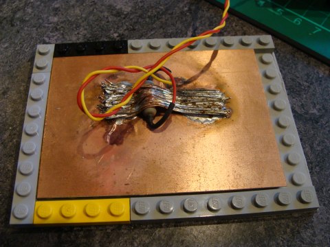
-
SNOOP_BURN will not be part of LUXPAK, but it is needed to store the RCX
firmware on serial EEPROM in the desired form.

|
|
- We still have to solve the problem of the
manipulations at start:
- LUXPAK needs to be switched on 1 hour
before launch, because of the warm-up time of the sensors.
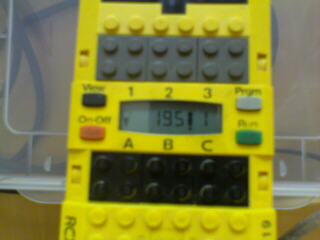
- The idea is to program the RCX to
manage the data sampling at the tested rate 7 records/min. In that
case, with record size being 24 bytes, the maximal datalogging time
is 32765/24/7=195 minutes
- Datalogging has been programmed in a
way that accidental erase of the EEPROM is impossible.
- Normally this should be sufficient: 1
hour before launch plus 2 hours flight
- But, if any troubleshooting delays the
launch, there should be a reset procedure.
- The alternative could be something
like http://www.unr.edu/nevadasat/BalloonSats/Balloonsat%20Pages/temp_trigger.html
that only starts the datalogging.
|
|
|
2008/05/11
|
|
- First temperature regulation tests with
the RCX:
- Test board:
- RCX with three 10Ohm resistors in
series connected to port A. (2 of them are 5W types, 1 is 3W
type -in fact 12Ohm this one)
- LEGO temperature sensor fixed to
one of the resistors as shown on picture below. Added thermal
grease between resistor and sensor.
- ==> voltage at port A is 9V and
current: 9/30=300mA; heating power: 9*0.3 =2.7W
- control program should try to
maintain the temperature at 40°C by reducing or increasing the
output power.
- easy control through slowly
increasing or decreasing the output power (no PID)
- the reaction of the system is
expected to be slow
- experiment duration: 30 minutes
- sampling rate: 1Hz
- ambient temperature: 23.5°C
- Experiments done with ULTIMATE ROBOLAB and
ROBOLAB INVESTIGATOR:

|
|
- Other experiment: Run everything on 6 x
1.2V NiMH batteries instead of the AC adapter:
- The RCX output voltage drops to less
than 6V (Philo says that we are loosing 1.3V in the output driver.)
- Battery voltage drops 0.2V only
- 50°C are never reached, so
motor-power remains 255 all the time
- the driven output port was connected
to SNOOP_LOG in order to see, if SNOOP_LOG switches to boot mode or
to datalogging mode. This test is made to see, if we can be loosing
the datalogging mode due to battery voltage loss. (Remember that
SNOOP_LOG checks one of the RCX output ports for voltage.)
- ==> even if the voltage falls
below 4.5V, SNOOP_LOG still recognizes the RCX and datalogging
mode is still set. But, even a very short drop below 4V,
triggers boot-mode.
- ===>
we should add a capacitor in parallel to the RCX output that
connects to SNOOP_LOG in order to prevent accidental loss of
datalogging mode. (Although this never happened in the
experiments.)
|
|
|
2008/05/12
- We could reduce the amplitude of the
temperature oscillations by simply dividing the main loop time by 2 and
increasing the motor power increments to 4 instead of 2.
- The experiment was done on brand new AA
alkaline batteries:
- The temperature rise time has grown,
because of the weaker current.
- ==> this simple control is
sufficient. no need to write a PID-controller that would fill the
firmware with plenty of code lines and thus increase the download
time and the risk of download error.
|
|
- Don't
forget to spray the bottom of SNOOP_LOG and Mootz-board with some
electrical isolating varnish. Question: at high altitude the
ionisation of the athmosphere is very intense. Could there be undesired
reactions with the board?
|
|
|
2008/05/14
- Our
payload has been selected for the H.A.L.E. activity this summer !!!
- We made an important change concerning the
LED indicators in order to solve the "1 hour before flight"
and "just before flight" issue leading to the following start
procedure: (NOTE : the function of the green LED has changed !!!! Yellow
LED takes over the role of old green LED. Don't confuse this new yellow
LED with the one SNOOP_LOG PC-board, which exclusively is used to
produce the reference voltage for the ADC.)
|
|
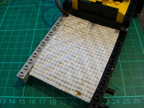
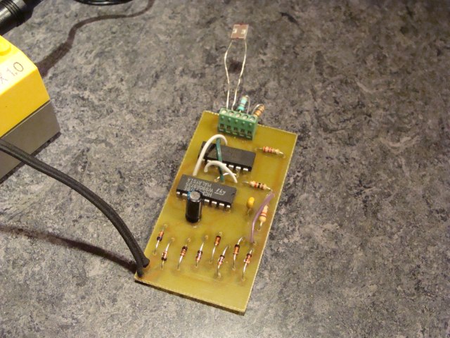
- SNOOP_LOG receives an open-loop heater. We
take a 100Ohm /1W resistor that we fix by soldering to a PC-board (no
electric connections to the board.) The resistor is powered from the RCX
PortC that also powers the YELLOW LED (former green LED) and that gives
SNOOP_LOG the voltage to know the RCX is running the firmware. The
radiator is placed beneath SNOOP_LOG with a glass-fiber (and a paper)
sheet between both to prevent any short circuit. There is no risk of
overheating, so this heater can be used in open loop technic.
- ==> We call this the 800mW
heater (9^2/100=810mW)
|
|
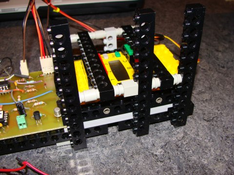
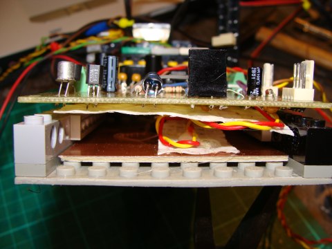
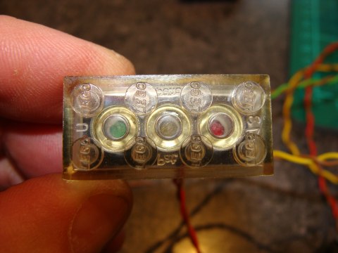
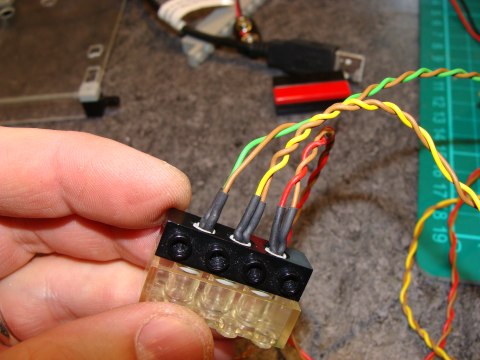
- The LED indicators have been placed inside
of LEGO 1/2 pins and a 1x4 Technic brick with a 2x4 transparent brick on
the front:
|
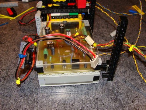
|
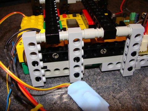
- SNOOP_LOG receives a transparent plastic
protection with 2 holes for the capacitors and another couple of holes
for the wires that connect to the RCX. Note the wires that pass between
the protection and the RCX.

|
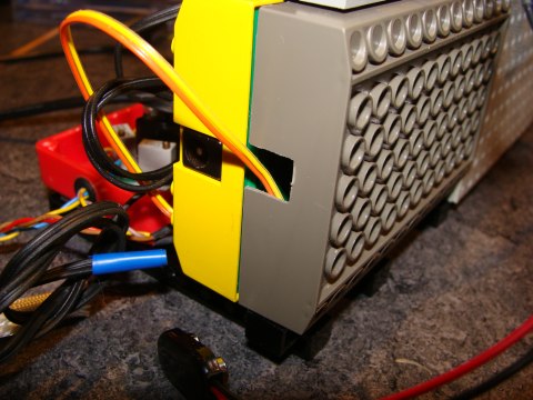
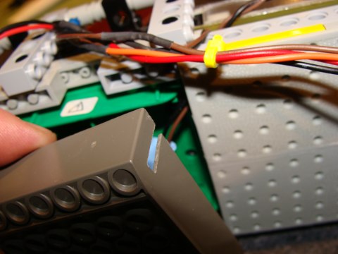
|
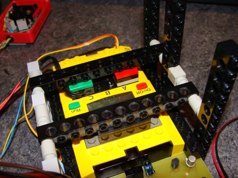
- The RCX bottom box has been cut in order
to allow the wires to pass to the outside. The box will receive the
optocoupler (between RCX on/off button and SNOOP_LOG) and later the
Mootz-board.
|
|
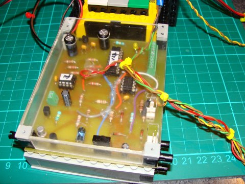
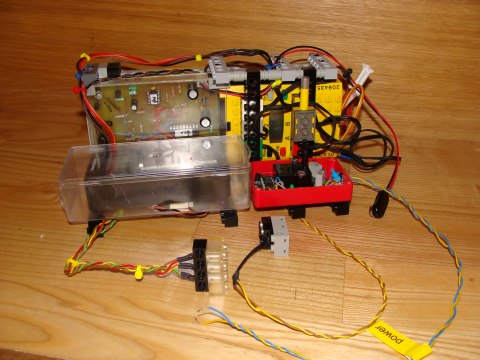
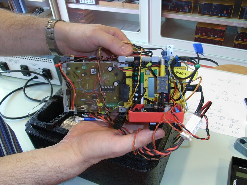
- General aspect of LUXPAK electronics so
far:
- Note the RCX button that will be used for the "REMOVE BEFORE
LAUNCH" device.
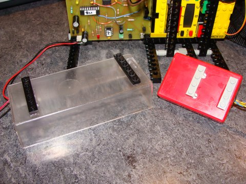
- Probably it's a good idea to add the top
of the red box to the pressure sensor
- Perhaps we will need to change the
ozone-sensor box.
- Also note the LEGO temperature sensor
that will measure the temperature of the payload interior.
|
|
|
2008/05/15
- We forgot to mention what the LEDs in fact
represent and how they are linked to the system:
- Red LED:
- owned by SNOOP_LOG
- flashes in the rythm of the
bootload-function
- flashes as data is stored on
EEPROM
- flashes on SNOOP_LOG error (see
above)
- Yellow LED:
- former green LED on SNOOP_LOG
schematics
- although placed on the PCboard of
SNOOP_LOG, this LED is completely powered by the RCX output C,
once the firmware is running and has executed the instruction to
set this port in forward mode at highest power
- normally ON while RCX firmware is
running
- flashes on system error (see
beneath)
- since this LED needs a bit more
current, we added another 3k9 in parallel to both already
existing (see above)
- Green LED:
- owned by the RCX
- powered by RCX sensor port 3 !
(set to "active" 9V-mode)
- goes ON when the "REMOVE
BEFORE LAUNCH" device is activated (we actually use a LEGO
touch sensor that will be maintained in "pressed"
state until the device is removed.
|
|
- We changed a few things in SNOOP_LOG
firmware:
- now the pause after error state is
much shorter
- error states (especially UART) are
cleared after sending the error message via LED
- we must activate the brown-out
protection in the configuration bits (this must be done manually in
ULTIMATE ROBOLAB FOR PICs as the Assembler-window appears). The
reason is that if SNOOP_LOG looses its voltage, there is enough
voltage from the connected electronics to maintain the uC in a
floating state. "BODEN_ON" detects this and maintains the
processor in reset state as long as the bad voltage condition
exists.
- now we have SNOOP_LOG fimware version
25
- get .hex
get .asm
- We designed the RCX firmware in ULTIMATE
ROBOLAB with the following functionality:
- Initialize the RCX with a short
selftest:
- actual version v11
- get .asm
.srec
- disable normal RUN-button function
(the firmware is stopped by switching off the RCX)
- NOTE: if switched off while
SNOOP_LOG is running, SNOOP_LOG still detects some voltage on
port C, it thinks there is no firmware on the RCX. So, it sends
the firmware, although the RCX doesn't answer. Then, SNOOP_LOG
switches ON the RCX and restarts sending the firmware. This may
take 10 minutes !!! (so, caution: switch off SNOOP_LOG before
the RCX !!)
- configure sensor ports
- write "LXPAK" to the
display
- go into error mode (all LEDs are
flashing):
- Error 1: One of the RCX
buttons is pressed (all should be free, so open the payload
and verify !!)
- Error 2: "REMOVE BEFORE
FLIGHT" - device already removed ==> at system start
(1 hour before launch), the device must be correctly in
place.
- Error 3: Temperature-sensor
not connected to RCX sensor port 2
- Error 4: Temperature-sensor
not connected to RCX sensor port 1
- Error 5: this error-state
cannot appear at start, but only later, if a reset procedure
has been executed ==> power off, wait a few seconds and
power on LUXPAK (SNOOP_LOG must be off voltage; it is
sufficient that the RCX is switched off manually - do this
after having unpowered SNOOP_LOG)
- now the RCX waits either for
"REMOVE BEFORE LAUNCH" or for the RUN-button pressed
- if the PRGM button is pressed,
the old data on EEPROM is send to the PC via RS232
- switch on green LED
- reset LUXPAK clock
- run "main task"
- test if RCX buttons have been
pressed (needed after payload recuperation in order to
retrieve data)
- if PRGM button is pressed,
a 0xF7 (2) message is sent to SNOOP_LOG, which then
transmits the contents of EEPROM to the PC via RS232
(there was a bug in the ULTIMATE ROBOLAB "send
message" function; we fixed it here -red/blue icon)
- after a PRGM button event
and data upload, the RUN button must be pressed to
resume datalogging
- if
the RUN button is pressed together with the PRGM button
(RUN button first) then the EEPROM buffer pointer is
reset and datalogging starts from scratch (if
accidentally done, SNOOP_LOG must be switched off and
sent back to us in order to recuperate the data.) SO,
CAUTION, WHEN MANIPULATING THE RCX !!!
- test if we have passed 2 hours
- switch off "heating
task"
- run "heating task"
- we try to maintain both
temperatures above 10°C (see above)
- run "sampling task"

|
|
- We made a long-time test with LUXPAK. Here
the results (data has been processed by LABVIEW:
|
|
2008/05/16
- The actual RCX firmware (version 11) does
not respect yet Francis'
suggestion to switch on the ozone tube heater some time before
launch. He also concluded that no other heater was necessary inside the
payload. Further Francis couldn't conclude from theory that the tube
heater was able to maintain the sucked in air temperature above 0°C at
-50°C outer temperature, although the practical tests are more
optimistic. For these reasons, Claude suggests:
- Install the 800mW heater beneath
SNOOP_board in order to maintain SNOOP_LOG under best conditions..
The air-heater is supposed to be enveloped into the isolation
material. Thus the temperature might not be equal through the whole
box.
- Have the possibility for a 2W box
heater.
- If the RCX is supposed to do the tube
heater switching directly, then the maximum power is 9V*0.4A=3.6W,
which is only half of Francis' proposal.
- ==> Install LUXPAK in a freezing
chamber at deepest possible temperature and have the system run for
an hour to see how everything works.
- Yesterday's
tests were executed on a simple test bench (see photo below). The graphs
show that there is no drift at constant device temperature.
|
|
- Some more information about SNOOP_LOG
 : :
- current:
- 6.6mA in wait state
- 6.6 - 7.3mA during datalogging
- 23.9mA during data upload
- 7.39 - 13.86mA during boot-loading
(current oscillates at about 0.5Hz)
- brown-out:
- PIC16F88 data sheet specifies that
if the uC voltage drops below 4V during more than 100us, then
the brown-out situation will reset the chip and maintain the
reset condition as long as the voltage doesn't rise over 4V.
- ==> low battery situation at
system start will be recognized through 1Hz red LED flashing
(probably SNOOP_LOG tried to bootload the RCX, but didn't
succeed due to voltage-drop. The chip falls into brown-out, but
since the current is reduced, the voltage may rise over 4V.
SNOOP_LOG restarts, but as soon as the IR-LED is activated, the
higher current forces anotheer voltage drop a.s.o.
|
|
- We received the accus from CONRAD
electronics today. Some data:
- Article 250407 !!! (They changed the
article...???)
- NiMH
- 1.2V
- 28g !!!
- max. discharge current : 3C
- no information about self-discharge
features
- batteries arrived well charged, so
we may suppose that they have low self-discharge characteristics
|
|
2008/05/17
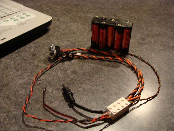
- Now
we also have a power-supply wiring bridge that distributes the battery
voltage to the different devices.
- Everything
may now be switched on through one single button.
- Note
that the RCX and the ozone sensor are powered through their AC or DC
adapter plug.
- Mootz_board
and the pressure sensor use the same free wire
- SNOOP_LOG
now also is powered with 12V.
|
|
- An important issue with LUXPAK/RCX firmware v.11
has appeared during system tests:
- Both RCX controlled temperature
sensors use the RCX ROM conversion from raw ADC value to 1/10°C.
- If the temperature grows beyond 60°,
the returned temperature is 9999.9 !!!
- The reason for this must be searched
in the conversion function of the NTC raw data. Because the RCX uses
integer values only, LEGO engineers choose a linearization method
that uses intervals of linear equations with the parameters shown in
the following diagram:
-
But the authors of the RCX
ROM function 0x14c0 added limitations. If raw values are strictly
smaller than 290 or greater than 928 then the function returns the
value 0x7FFF, which is displayed by 9999.9, since the RCX display
cannot show larger numbers.
-
Nothing prevents us from
using the first and the last linearization parameters for raw values
out of the ROM range. The only condition is that the sensor values
cannot be used directly, but must be verified and adjusted before use.
|
|
- Since we are using an original LEGO
temperature sensor inside of the box and a NTC thermistor from the shelf
(CONRAD part number 195596), we must calibrate this sensor.
- Datalogging the temperature values of both
sensors during a simple experiment shows that they are almost simply
offset by :
|
|
|
|
|
- We accidentally pressed both buttons
(RUN/PRGM) together, where we should have pressed the PRGM button
alone... and the RCX sends the fatal message 0xF7 (0x39) to
SNOOP_LOG which resets the EEPROM buffer pointer and puts LUXPAK
into ERROR 5.
- ==> we absolutely need another
button combination that will not be possible with one finger. As
is, LUXPAK gives not well access to the RCX VIEW and ON/OFF
buttons. Thus, we will instead use the combination RUN/VIEW. The
combination PRGM/ON_OFF produces an RCX reset. It won't be
possible to press the RUN and the VIEW buttons with one
finger... accidental erase is avoided.
- ==> we also need clear user
guidlines for LUXPAK troubleshooting in the case of errors.
|
|
Important
detail that we forgot to mention so far:
|
2 of the
crew members are hams: Jean Mootz LX1SK and Claude Baumann LX1BW |
|
The
Convict Episcopal's ham identification number is LX9CC |
|
|
2008/05/18
- Note to yesterday's temperature test: the
RCX was placed inside of a non-isolated - but air-proof- box in a normal
freezer at -18°C during one hour. At the end of the experiment, at the
opening of the box, the RCX was completely wet, which could be fatal for
electronics. We conclude from this experiment that we will need inside
of LUXPAK:
- silica-gel to absorb as much as
possible humidity during the warm phase of the flight
- keep the box interior warmer than the
dew point
- QUESTION:
how does the dew point evolve during ascension?
- Operated
another long-duration test in order to measure the increase of the
temperature inside of the box and next to SNOOP_LOG board (800mW
heater):
- LUXPAK
was first placed in an environment at 13°C during 3000sec, then at
ambient temperature of 23°C
- The
polystyrene box was closed
- Except
Mootz_board, the box-heater and the tube heater system, every device
was powered
- Ozone-sensor
accus was completely empty
- Use
of new accu-pack
- ==>
Observations:
- Ozone
sensor heats to about 35°C
- Box
temperature rises, if the outer temperature higher
- 800mW
heater reaches an unregulated steady state temperature that
is about 20° above the outside temperature
- box
temperature doesn't rise at low outside temperature
- RCX
regulates the voltage very, very carefully: no variation -
astonishingly - compared to the previous tests with the
AC-adapter
|
|
2008/05/19
- This stratosphere balloon activity is not
gender specific. The Ecole
Privée Fieldgen for girls is going to launch a meteo balloon with a
payload that measures temperature, pressure, light intensity and takes
photos during the ascension. The data is directly sent by radio to the
ground. It doesn't seem that they worry about the temperature inside of
the payload box. However they wrap aluminium foil around the box. Great
project !
|
|
Fieldgen,
Luxembourg's most known private school for girls is launching a meteo-balloon
to the stratosphere from the center of Luxembourg-City |
|
2008/05/20
- Jean Mootz an d Francis Massen worked hard
on the calibration of the PT100 temperature sensor. Because Mootz_board
isn't temperature compensated they experimentally established
calibration functions for various temperature classes. Mootz_board will
be placed inside of the battery-pack. The RCX electronics will probably
provide enough heat to maintain the board in a most linear section.
- They also worked on the ozone-sensor
air-heating problem. Using a very sensitive and rapid temperature
sensor, they tried to heat an air-flow at different speeds and
temperatures. Francis will present a detailed report of the experiment.
Even after the experiment it is not clear, if we will succeed to heat
the air to more than 0° at deep ouside temperatures. The best idea is
to use a magnetic pneumatic valve, let in a certain quantity of air that
is heated and sucked to the ozone sensor. Francis looked around and
could not find any LEGO magnetic valve. However there exists one from
Fischer Technik.
|
|
2008/05/22
- Yesterday's meeting with Francis:
- We repeated the air-heating experiment
and decided that it probably will be sufficient to control the flow
by reducing the diameter of the tube. The main silicon tube has an
outer diameter of 6mm that is needed to have contact with the
resistors. But we will add a reduction at the outlet in direction of
the ozone sensor.
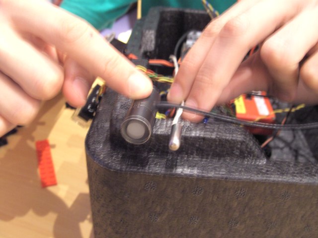
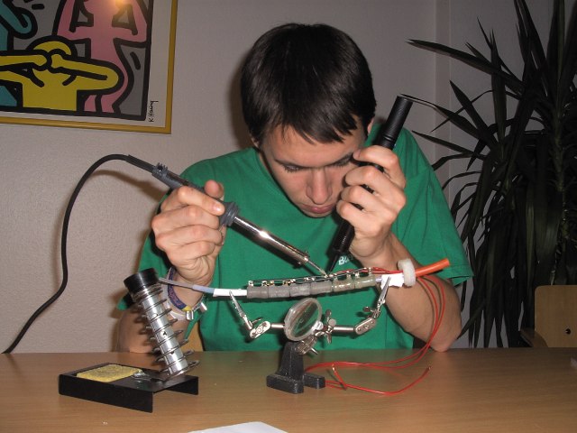
- Here Claude while repeating the
simulation of the ascension air-flow:
-
We decided to add about 100g
silica-gel to LUXPAK. (It must be reactivated.)
-
The air-tube heating will be
definitely powered by the RCX. Inside of the isolation pack, the RCX
will then try to maintain a temperature of 100°C to heat both the tube
and by dissipation also the LUXPAK interior. No other heater (except the
SNOOP_LOG 800mW heater) will be needed. However, the heating resistors
will be distributed over two RCX output ports. There are 6 resistors of
30Ohm each. If they are soldered like indicated on the schematics below,
each RCX port will be loaded with 30*60/(30+60)=20Ohm and the maximal
current will be 450mA, that we already tested with the RCX. The resistor
block needs about a quarter of an hour to be heated at 100°C, that
could be effectuated during the phase of the ascension through hot air.
The steady state inside of the isolation block is about 150°C. Inside
of LUXPAK this probably would be higher, since the heat is dissipated in
a worse way. Anyway, the RCX will regulate the temperature to 100°C. As
a security, there are:
-
the RCX driver current
limitation
-
the RCX fuse (this would
be fatal, because LUXPAK woulod be dead. But, as Philo says, the
fuse only reacts at 1.5A)
-
the inner temperature
sensor that will tell the RCX that there should be a heating
reduction.
-
We also soldered the
pressure sensor and Mootz_board to the main power supply.
-
Many thanks to LCD meteo for
all the expensive sensors and pieces (like the silicon tubes).
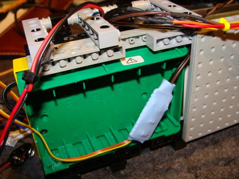
-
Some studs of the RCX
battery pack had to be cut to accept Mootz_board. (Sorry LEGO). Note the
400Ohm resistor that has been added to the board. (Schematics
still missing.)
|
|
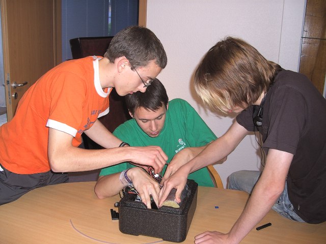
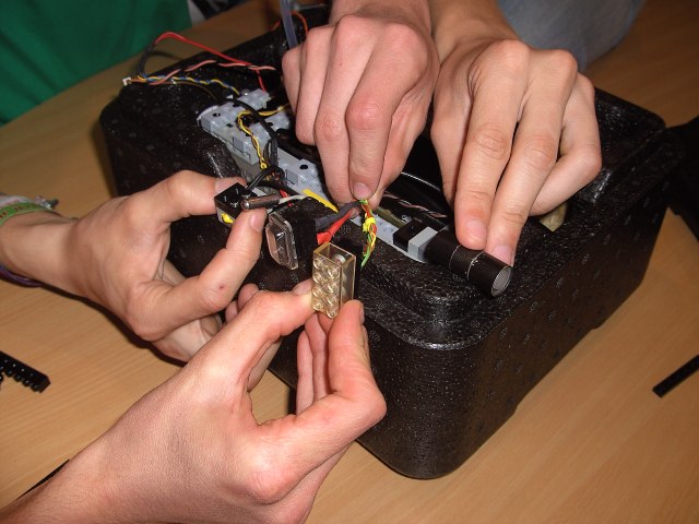
- The students group worked on the rather
complex problem of how to fix LUXPAK's interior to the polystyrene box.
One evening of discussions, tries and errors. But, unlike normal LEGO
engineering, some trials cannot be done, because they need cutting and
glueing. In this case, solutions have to be anticipated and well
reflected, because they cannot be "un-done".
-
The group decides to place
the battery pack, where the Ozone sensor was placed before. LEGO plates
and bricke will be added to hold it. One major issue is that another
tube must pass through the payload, where the balloon-string is passed
through. We first thought of using a rigid aluminium tube, but the
thermal conduction will make of it a freezing element inside of the box.
Francis suggested to use a silicon tube instead. Eric Wang reported in
an email that they are commonly using a drinking straw. Anyway, the
string passing through the payload causes a major problem of the
disposition. Here the position of the accu pack:
-
The buttons and LEDs will be
fixed on the box side. First idea was to fix the PT100 on the same side,
but as the sun may shine on it, there could be useless values. The
light-sensor is fixed to the bottom, as excentrically as possible, to
avoid to many influences of the payloads that might be fly below LUXPAK.
PT100 will be fixed in proximity to the light-sensor (simply glued to
drilled holes.)
|
|
- Last-minute proposal:
- Mootz_board requires the information
of the board-temperature because of the temperature-characterstics
- We were not able to establish a
concluding theoretical model for the ozone tube heating. It would be
most interesting to control the temperature at the ozone-sensor
entrance
- The temperature of LUXPAK interior
must be known, in order to prevent overheating, or deduce, if our
heating perhaps was insuffcient
- ==> rapidly build Mike
GASPERI's RCX input mux and use 3 NTCs (10k at 25°C) on one
RCX input port instead of the original LEGO temperature sensor
- add a 2-bit marker to the sensor
value in order to let SNOOP_LOG and later the PC identify the
specific sensor
- A new Gasperi input multiplexer was
prepared in EAGLE in half an hour, etched and soldered in 1 hour and
tested in another half an hour. Everything works fine. We only
replaced the 2k2 with a 1k resistor and the 3k9 (3k3) with the 2k2.
This returns lower values, where more linearity can be expected for
the NTCs, but the RCX sensor percent mode can no longer be applied:
-
For the first tests we
used two fix resistors and 1 CdS light sensor. The RCX was programmed
that a single pressing of the RCX PRGM button would shortly toggle
from "reflection" type to "switch" type, keeping
the mode always "raw". Mike's reference point, where the
sensor returns 100% in percent mode corresponds to a raw value of 308
(through 1k resistor). A 10k resistor on one of the inputs returns 660
and a 3k9 resistor returns 530. We now will proceed to the NTC
calibration and reprogram LUXPAK's RCX according to all the new
requirements.
|
|