![]()
Controlling the inverted pole

created 31.08.06
last update 07.09.06
Most Mindstormers should know Steve Hassenplug's famous self-balancing LEGWAY and Philo's adaptation to NXT. The absolute top self-balancing robot robot however is a metallic CMU realization !!!
We want to learn more about the problem of controlling an obviously instable construction.
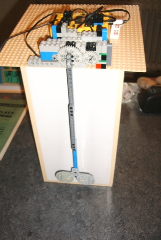
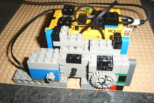
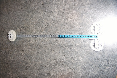
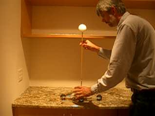
1. A simple experimental set-up :
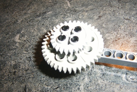
2, The pendulum
3. Pendulum oscillation
From physics we know that a pendulum has one stable position where the potential energy is minimal. Of course this is the vertical position with mass down. Our pendulum has a length of 32cm. A mathematical pendulum should present an oscillation period of :
But, since the mass is not regularly distributed, we must deduce the reduced length from the observation. Through a datalogging RCX program we collect the evolution of the oscillation-amplitude and the angular velocity from which a period of 1.11sec can be deduced that is very close to the theoretical length.
|
|
Observation : As usual the rotation-sensor doesn't return very accurate values, since the resolution is only 16 rotation pulses per whole shaft rotation. This is visible in the staircase shaped graph. |
|
|
Observation
: The tachometer returns very precisely the angular velocity of the
pendulum. The use of the tachometer also helps to overcome problems of
computing the derivate during operation. The issue first is the short generated
delay that appears between the computed and the
real derivate and second the tendency of the computed derivate to present
many peaks and wells that don't exist in reality being the result
of high frequency variations caused by the sampling process as can be seen
below.
|
|
|
From the absolute values the
damping factor can be deduced as the mean of the peak to peak ratios :
1.56
Note that the raw tacho values oscillate around the middle value 512. Due to the motor-coils high-frequency disturbances must be filtered out. We do this through an infinite response filter : mean = (mean + sensor_value + 512) / 3, the starting value being 512. The conversion to rotation-sensor increments per second follows the equation :
|
|
|
The damped oscillation can be represented in the phase diagram as a spiral. |
The RCX program uses the following prelude to compute the angle and the angular velocity :
3.1. Theoretical consideration of the undamped pendulum
At any moment t, the gravitational force and the inertial force are exactly opposite.
|
This represents a very complex differential equation that can be simplified :
|
|
|
The angle is a function of time :
Doing the Laplace transform :
With the inverse Laplace transform :
|
3.2. Theoretical consideration of the damped pendulum motion
Adding a damping effect to the movement changes the reaction of the pendulum as demonstrated on the above plots. Friction in the system may be considered as dependent on the velocity Fr=bj' and the equations change to :
|
Doing the Laplace transform :
Applying
the first shifting property of the Laplace transform
This equation represents a damped oscillatory motion. This equation describes a critically damped motion, since any decrease in the damping constant would produce oscillations.
The motion that is represented by this equation is called overdamped motion and is non-oscillatory. |
Link : http://www.abdn.ac.uk/physics/vpl/pendulum/harmonic.html
4. P-controller
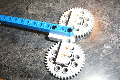
We need a control device to move the pendulum from the stable position to the instable inverted position. The first try is a P-controller. The motor-power is calculated proportionally to the difference between stable and instable angle (180° e.a. 40 rotation increments; note that the system has a 40 to 8 gearing). For any reason - probably the motor torque - the oscillation period is slightly increased to the free oscillating pendulum.
This program produces the following reactions:
Note : of course the power is clipped to Ultimate ROBOLAB maximum power +/-255 by the motor controller.
5. PD-controller
Adding the derivate of the angle which is the angular speed to the controller, changes the reaction of the system. The oscillation period is shortened a bit and there is a better damping. See the video !
6. The cart and the inverted pendulum
Balancing the inverted pendulum on a mobile cart through the cart acceleration is far more complicated than balancing it on a fix system with direct motor power. Well-known Mike Gasperi, one of the early RCX sensor specialists, sent us this video of his NXT driven cart and the NXT program:
 Thanks Michael !!! A simple P-controller is already
able to maintain the pole for a certain time.
Thanks Michael !!! A simple P-controller is already
able to maintain the pole for a certain time.

Also consult the following links :