

Robolab 2.5 Piano file (really sounds like the film-tune)
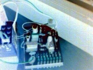
Audio frequency sensor
created 10/08/2002 updated 11/08/2002
We have already dealt with different aspects of sound in some projects: sound-sensor, sound-peak detector, phase sound sensor, IR/ultrasonic-beacons. Now we propose a simple but impressive audio frequency sensor for the RCX.
Do you remember that tune from the immemorable Steven Spielberg film "Close Encounters of the third kind"? Spielberg plays with this Leitmotiv, even making sound visible by fantastic light effects.
Our device-tests will turn around the third kind's tune.
 |

Robolab 2.5 Piano file (really sounds like the film-tune) |

|
1. Some sensor features
2. Schematics Click to enlarge
Download CADSOFT Eagle 4.01 schematics
The device is made of a regulated power-supply, an audio-amplifier stage, a comparator stage with stabilized reference-voltage, a microcontroller with its external oscillator, a LED-net and an integrator for the PWM-output of the PIC.
The principle is simple: during a fixed time (a quarter of a second), the microcontroller counts the pulses at one of its input-lines. The LEDs show the 8-bit representation of the number of pulses (devided by two). The microcontroller's 10-bit Pulse Width Modulator (PWM) is powered during number of pulses / 1024 of the time.
This leads to a device voltage-output [range: 0 - 5V] which is proportional to the detected frequency :
U / 5 = ( f / 4 + 256 ) / 1024 , U [ V ] f [ Hz ] FORMULA 1
NOTE: the number 256 is added because of the operating range of Mike Gasperi's RCX-buffer. Thus the minimum output-voltage is 1.25V
3. Part-list
| Part | Value |
| C1 | 100nF |
| C2 | 100nF |
| C3 | 220uF |
| C4 | 100nF |
| C5 | 100nF |
| C6 | 22pF |
| C7 | 22pF |
| C8 | 220nF |
| C9 | 1uF |
| C10 | 68nF |
| D1 | LED3MM (low-cuurent) |
| D2 | idem |
| D3 | idem |
| D4 | idem |
| D5 | idem |
| D6 | idem |
| D7 | idem |
| D8 | idem |
| IC1 | 78L05 |
| IC2 | LM324N |
| IC3 | PIC16F628-20P |
| Q1 | 18.432MHz |
| R1 | 3k3 |
| R2 | 100k |
| R3 | 3k3 |
| R4 | 1M |
| R5 | 15k |
| R6 | 100k |
| R7 | 1k |
| R8 | 10k |
| R9 | 2k2 |
| R10 | 2k2 |
| R11 | 2k2 |
| R12 | 2k2 |
| R13 | 2k2 |
| R14 | 2k2 |
| R15 | 2k2 |
| R16 | 2k2 |
| R17 | 1M |
4. PC-Board
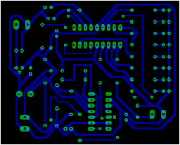
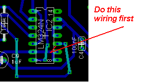
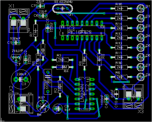
Download CADSOFT Eagle 4.01 PCboard
Put attention not to exchange supply-polarity. This will at least destroy the PIC !!!
5. PIC-program
This time we opted for the PIC 16F628, which is 100% backward-compatible with the 16F84 (not vice-versa!!!). Among its additional features, the 16F628 has an on-board PWM, that we engage here.
CHFlashBasic-program:
PIC 16F628
FREQ 18.432
OSCILLATOR CRYSTAL
BYTE Pauses
WORD Pulses,Pul_div_2
     IR_Ext_Begin
        Pulses=Pulses+1
     IR_Ext_End
     '
     'configure Ports, RB0 is ST-input
     'RB3 is reserved for the PWM
     '
     SetPort A , %00000000
     SetPort B , %00000001
     '
     'wait a bit
     '
     DELAY 1000, 0
     '
     'clear variables
     '
     Pulses=0
     Pauses=0
     '
     'configure and enable RB0 edge-interrupt
     '
     Interrupt_Ext 1, rising
     Interrupt_Enable
     '
     'configure and enable PWM
     '
     PWM_Config 888.099, 0, 1, 0
     '
     '
     'Main Loop
     '
LOOP :
     'waiting 1/4sec provides us a 4Hz resolution
     DELAY 250, 0
     IF PULSES<>0 THEN
        'LED-8bit output at 8Hz
        '
        Pul_div_2=Pulses/2
        *MOVF PUL_div_2_L,W
        *ANDLW B'11110110'
        *MOVWF PORTB
        *MOVF PUL_div_2_L,W
        *ANDLW B'00001001'
        *MOVWF PORTA
        '
        'PWM at 4Hz
        'The next line is to overcome 0.67V problem
        Pulses=pulses+256
        *MOVF Pulses_H,W
        *ANDLW B'00000011'
        *MOVWF Pulses_H
        *ANDLW B'00000011'
        PWM_Reg Pulses, 1
        PULSES=0
     ELSE
        'wait 1sec to reset if 0 Hz
        Pauses=Pauses+1
        IF Pauses>2 THEN
           Pauses=0
           PortOut A , %00000000
           PortOut B , %00000000
           PWM_Duty 0, 1
           Pulses=0
        END IF
     END IF
     '
     GOTO LOOP
|
IMPORTANT NOTE: CHFlashBasic V. 3.6.0 has a subtil bug in the PWM-configuration, which appears while the program is compiling FlashBasic to PIC-Assembler (MPASM). You must change this manually in the MPASM-file.
....
; CONFIGURE AND ENABLE PWM
     ;
     CLRF   TMR2
     MOVLW  255
     BSF    STATUS, RP0
     MOVWF  PR2
     MOVLW  0
     BCF    STATUS, RP0
     MOVWF  CCPR1L
     CLRF   CCP1CON
     MOVLW  B'00001111'
     IORWF  CCP1CON, F
     MOVLW  0
     IORWF  CCP1CON, F
     BSF    STATUS, RP0
     BCF    TRISB, 3     ;<---- CHFlashBasic bug (2 is not 3)
     BCF    STATUS, RP0
     BSF    T2CON, TMR2ON
     BSF    STATUS, RP0
     BCF    PIE1, TMR2IE
     ;
     ;
     ; MAIN LOOP
     ;
LOOP
..... |
Download
6. Robolab-tests
Here the datalogging-program ! Note the new Powered sensor container.vi which may be found as part of one of the patches at Tufts University's Robolab Site .
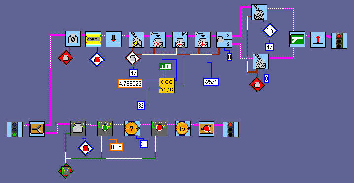
The RCX recorded the sensor-data given by Spielberg's tune played on Robolab 2.5 Piano. The result is the frequency in Hz.
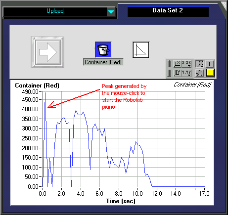
According to Mike Gasperi's buffer specifications, formula1 may be transformed to:
f = 4.789523 * Raw-value - 2571.159588 , f [ Hz ] FORMULA 2
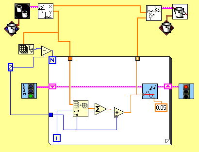
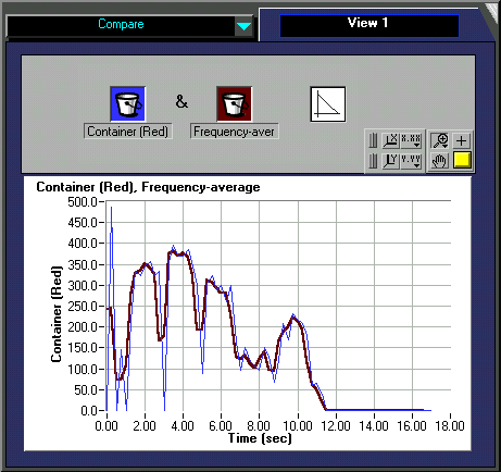
The following COMPUTE-level5 program will average the data a bit and create a downloadable RCX program that will produce the tune back. You'll recognize Spielberg's tune. This might of course never be a HiFi-application, but a way to prove the sensor's quality.
11/08/2002 update
We have found another bug in the CHFlashBasic software. While configuring the rising edge interrupt, you must set the INTEDG-bit in the OPTION-register. CHFlashBasic misses to select the correct before. So we manually added the following red line to the program. Without this the program works, but the interrupts are generated at falling edges.
.... ; CONFIGURE AND ENABLE RB0 EDGE-INTERRUPT
;
BSF STATUS, RP0
BSF OPTION_REG, INTEDG
BSF INTCON, PEIE
BSF INTCON, INTE
BSF INTCON, GIE ....
We also found out that the PWM is reset everytime PORTB is written to as a whole register. This causes a certain frequency-dependent voltage drop at our device output. Now we write only to single PORTB-bits.
When reading the number of pulses stored in variable PULSES we must make sure, that this variable is not changed outside of our quarter of a second task. So we first disable edge-interrupts, read and write to PULSES, then enable interrupts again.
Download new PIC-files: