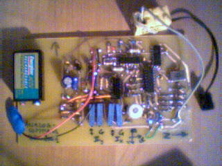
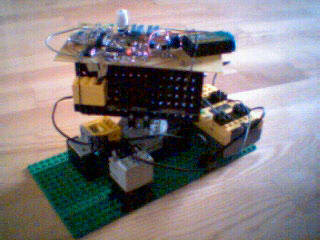
 prototype
PIC-Compass
Another attempt to make a useful electronic compass with the Pewatron-sensor.
(last update 28/12/01)
prototype
The idea this time is to overcome the limit of using two RCX input-ports AND the nasty calibrating operations. This is really challenging, because you need to compute at least two directional informations to get the correct compass-azimuth. So you must add some intelligent electronics which may operate parts of the work done by the RCX in our previous projects.
Again we are working with the PIC 16F84. This is not the best choice at all from the technical point of view, for we actually would need :
The micro-controller has to read the amplified sensor-voltages, convert them to digital infomation, compute the azimuth-computations and put out a voltage to be transferred to the RCX.
Nevertheless we decided to use the PIC 16F84 for DIDACTICAL reasons. Some of our students learn how to program this chip. So, here a marvelous exercise to push themselves and the micro-controller to their limits. We also decided to use the well-known LM 324, the 339 and the analog switch 4066. The students have to deal with the limits of these chips too. After this project every participant will definitely know the value of a rail-to-rail amplifier !
1. The circuit
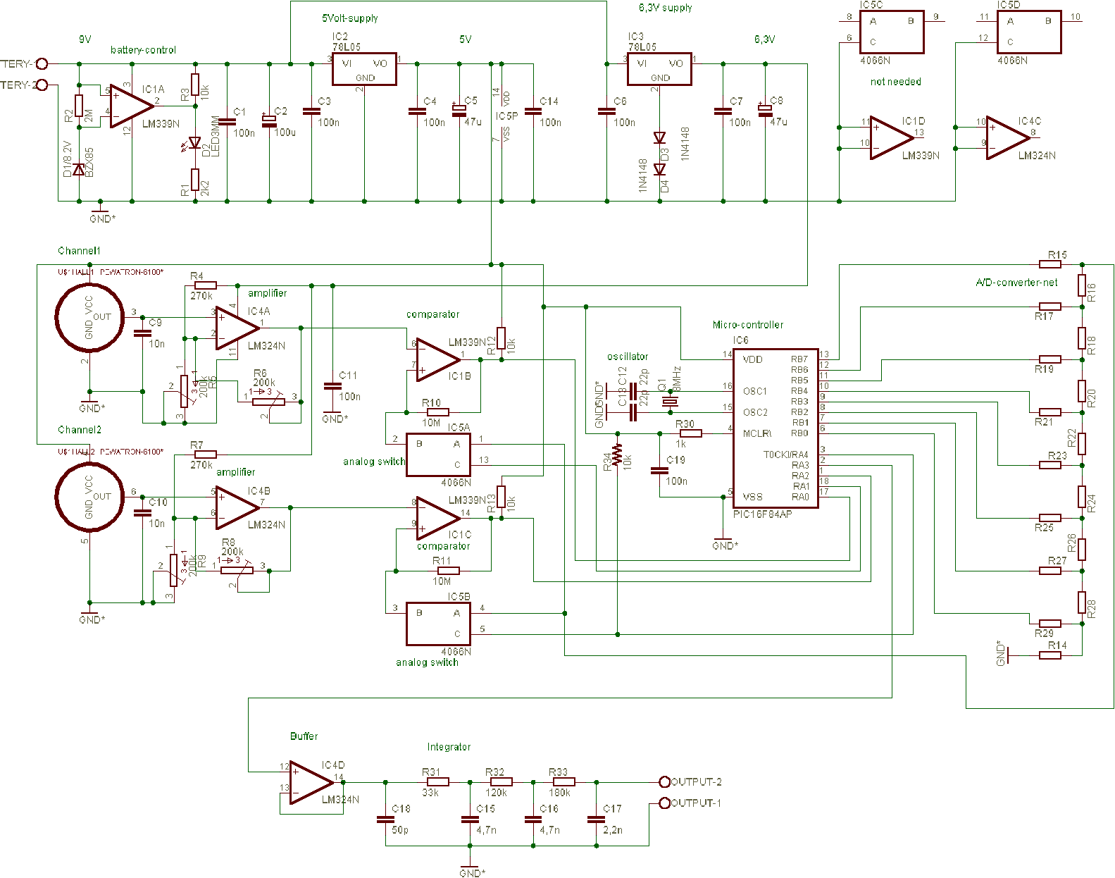
(Don't forget the single wire !)
To overcome the complicated calibration and standardization of our former projects, this device is equipped with a monitored stabilized power supply. It needs 9V DC and provides 5V, 6.3V and 9V.
Let's have a look at one channel :
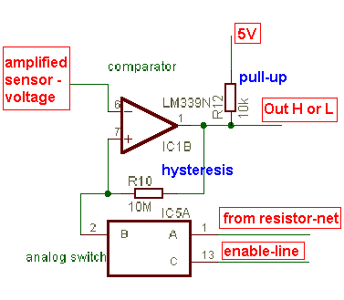
The slightly damped Pewatron-signal is read, then amplified and sent to a comparator. Note that the LM 324 amplifier is powered by 6.3V, not being a rail-to-rail op-amp.
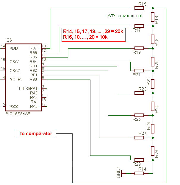
By enabling the correct analog switch, the PIC leads the voltage from the resistor-net to the comparator. This is an inverted application of our D/A converter. The PIC counts from 0 to 255 and will generate a growing voltage from 0 to 5V. Note that the RA4 is an open-drain port when configured as an output. So, it must be pulled-up by R34.
The output of the 339-comparator is pulled-up to 5V ! This is not an error of design since the 339 is powered by 9V, but a legal application of this chip's open-collector output.
If the voltage from the resistor-net reaches the sensor-voltage, the comparator output switches from logical LOW to HIGH, telling the PIC to stop counting at PORTB, which is the resistor-net driver. Now the PIC is able to interprete the voltage as an 8bit value.
To avoid oscillations at the switching voltage, a 10M resistor is added providing a certain hysteresis.
It is important to well adjust both channels to work between 1.5 and 4.5V. The adjusting is done through the 4 potentiometers. This provides a common midth-voltage of 3V (e.a. 256*3/5 = 153). Thanks to the stabilized power-supply and this one-time adjusting, this compass must not be calibrated later.
The PIC returns the azimuth in a 2° resolution as a voltage within the range of 0 to 5V. We use the pulse width modulator (PWM) explained at the D/A converter page. As the 16F84 has no on-board PWM, we have to simulate one through an astute time-interrupting process. Neither a 0V, nor a 5V output will be possible, because the interrupt service routine needs some time. To gain speed, the PIC is clocked at 8 MHz.

2. The PIC-program
2.1. The A/D conversion
The scenario is the following :
 ; JUMP TO MAIN PROGRAM
     GOTO   START
     ;
     ; HERE THE READINGS OF THE CHANNELS
LOOP_1
     ;  WAIT 0.01MS
     MOVLW  12;*
     MOVWF  AUX1_H;*
DELAYLAB21;*
     MOVLW  52;*
     MOVWF  AUX1_L;*
DELAYLAB11;*
     DECFSZ AUX1_L, F;*
     GOTO   DELAYLAB11;*
     DECFSZ AUX1_H, F;*
     GOTO   DELAYLAB21;*
     ; SKIP IF COMPARATOR 1 IS HIGH
     BTFSS PORTA,0
     GOTO   COUNT_1
     ; NOW WE HAVE THE FIRST VALUE TO BE STORED
     MOVF   PORTB, W
     MOVWF  X
     GOTO   CONTINUE_1
     ;
LOOP_2
     ;  WAIT 0.01MS
     MOVLW  12;*
     MOVWF  AUX1_H
DELAYLAB22;*
     MOVLW  52;*
     MOVWF  AUX1_L;*
DELAYLAB12;*
     DECFSZ AUX1_L, F;*
     GOTO   DELAYLAB12;*
     DECFSZ AUX1_H, F;*
     GOTO   DELAYLAB22;*
     ; SKIP IF COMPARATOR 2 IS HIGH
     BTFSS PORTA,2;*
     GOTO   COUNT_2
     ; NOW WE HAVE THE SECOND VALUE TO BE STORED
     MOVF   PORTB, W
     MOVWF  Y
     GOTO   CONTINUE_2
     ;
     ;
START
     BCF    STATUS, RP0
     ;
     ; CLEAR PORT B
     MOVLW  B'00000000'
     MOVWF  PORTB
     ;
     ;  ENABLE CHANNEL_1
     BSF    PORTA, 1
     ;
COUNT_1
     BCF    STATUS, RP0
     INCFSZ  PORTB,F
     GOTO   LOOP_1
     ;
CONTINUE_1
     BCF    STATUS, RP0
     ;  DISABLE CHANNEL_1
     BCF    PORTA, 1
     ; CLEAR PORTB
     MOVLW B'00000000'
     MOVWF PORTB
     ;  WAIT 0.01MS
     MOVLW  12;*
     MOVWF  AUX1_H
DELAYLAB23;*
     MOVLW  52;*
     MOVWF  AUX1_L;*
DELAYLAB13;*
     DECFSZ AUX1_L, F;*
     GOTO   DELAYLAB13;*
     DECFSZ AUX1_H, F;*
     GOTO   DELAYLAB23;*
     ; ENABLE CHANNEL_2
     BSF    PORTA, 4
     ;
COUNT_2
     BCF    STATUS, RP0
     INCFSZ PORTB,F;*
     GOTO   LOOP_2
     ;
CONTINUE_2
     BCF    STATUS, RP0
     ;  DISABLE CHANNEL_2
     BCF    PORTA, 4
     ;
;NOW OPERATE THE QUADRANT AND CASE ANALYSES, THE DIVISION X/Y ;AND THE ATAN-FUNCTION, FINALLY COMPUTE THE ANGLE GOTO START |
Note that the delays-functions were made with CH Flash Basic.
2.2. The quadrant and the case discussion
Have a look at our former compass projects for better understanding.
This program-part has been created with CH-Flash-Basic. The software interpretes the BASIC-code and returns PIC-assembler.
PIC 16F84
FREQ 8
OSCILLATOR CRYSTAL
BYTE quadrant,case,angle,x,y,midth,dx,dy,temp
WORD phi,q,temp2
Start :
     'Quadrant
     IF x>midth THEN
        dx=x-midth
        IF y>midth THEN
           dy=y-midth
           quadrant=1
        ELSE
           dy=midth-y
           quadrant=2
        END IF
     ELSE
        dx=midth-x
        IF y>midth THEN
           dy=y-midth
           quadrant=4
        ELSE
           dy=midth-y
           quadrant=3
        END IF
     END IF
     '
     '
     'Case
     IF dx>dy THEN
        case=1
        temp=dx
        dx=dy
        dy=temp
     ELSE
        case=2
     END IF
|
2.2. The multiplying by 100
For speed and memory-economy reasons we wrote this useful multiplication of a byte by 100. The result is stored in the variable q (word-length).
;
MUL_AUX
    	CLRF	AUX1_H
	MOVF	DX,W
	MOVWF   AUX1_L
ROT
	BCF	STATUS,C
	RLF	AUX1_L,F
	RLF	AUX1_H,F
	DECFSZ	AUX
	GOTO	ROT
	MOVF	AUX1_L,W
	ADDWF   Q_L,F
	MOVF	STATUS,W
	ANDLW   B'00000001'
	ADDWF   Q_H,F
	MOVF	AUX1_H,W
	ADDWF   Q_H,F
	RETLW	0
;
;
;
;HERE THE MAIN PROGRAM BODY ..... ;SOMEWHERE : ;&&&&&&&&&&&&&&&&&&&&&&&&&&&&&&&&& ; HERE THE ANGLE COMPUTATIONS ; Q=100*X ; COUNT=Q / Y ; PHI = ATAN(COUNT) CLRF Q_L CLRF Q_H BCF STATUS,C ; MUL_100 MOVLW 6 MOVWF AUX CALL MUL_AUX MOVLW 5 MOVWF AUX CALL MUL_AUX MOVLW 2 MOVWF AUX CALL MUL_AUX ; AND SO ON AND SO ON ... |
The algorithm is simple :
100 = 64 + 32 + 4 = 26 + 25 + 22
example:
132 * 100 = 132 * (26 + 25 + 22) = 132 * 26 + 132 * 25 + 132 * 22
according to the distributive rule.
Multiplications by 2 are very easy to be done in Assembler, since you only have to rotate left the byte by one :
132 = 0x84 = B'1000 0100'
132 * 2 = B'1 0000 1000' = 0x108
2.3. The division (word by byte)
; ; DIV16_8 CLRF COUNT MOVF DY,W LOOP_DIV SUBWF Q_L,F BTFSC STATUS,C GOTO INCREMENT NEGATIVE MOVF Q_H BTFSC STATUS,Z ;SKIP IF NOT ZERO RETURN DECFSZ Q_H GOTO INCREMENT INCREMENT INCF COUNT GOTO LOOP_DIV ; ; ;HERE THE MAIN PROGRAM BODY ..... ;SOMEWHERE : ; DIVIDE CALL DIV16_8 ; AND SO ON AND SO ON ... |
This is the shortest way we could do the division, not the quickest. But the algorithm has the advantage that the PIC does not get lost in a loop, if division by zero or some undesirable overflow-error, which never should happen, but since Murphy's laws we are aware! The alogirithm is again very simple :
2.4. The atan-function
  ; TO CALL Y=ATAN(X):
     ; MOVF X,W
     ; CALL ATAN
     ; MOVWF Y
     ; NOW THE ATAN TABLE
ATAN
     ADDWF PCL;*
     RETLW 0;*1
     RETLW 1;*2
     RETLW 1;*3
     RETLW 2;*4
     RETLW 2;*5
     RETLW 3;*6
     RETLW 4;*7
     RETLW 4;*8
     RETLW 5;*9
     RETLW 5;*10
     RETLW 6;*11
     RETLW 6;*12
     RETLW 7;*13
     RETLW 7;*14
     RETLW 8;*15
     RETLW 9;*16
     RETLW 9;*17
     RETLW 0XA;*18
     RETLW 0XA;*19
     RETLW 0XB;*20
     RETLW 0XB;*21
     RETLW 0XC;*22
; AND SO ON AND SO ON ... |
This look-up table-function is extremely quick. It uses the particular feature which makes it possible to increment the program-counter proportionally to the function-operator. The program jumps to the given line, then returns from the call with the litteral value placed in the accumulator.
2.5. The azimuth
; ;HERE THE MAIN PROGRAM BODY ..... ;SOMEWHERE : CH-Flash-BASIC code '
phi_H=0
IF quadrant=4 THEN
IF case=1 THEN
phi=90-phi
END IF
END IF
'
IF quadrant=3 THEN
IF case=1 THEN
phi=90+phi
ELSE
phi=180-phi
END IF
END IF
'
IF quadrant=2 THEN
IF case=1 THEN
phi=270-phi
ELSE
phi=180+phi
END IF
END IF
'
IF quadrant=1 THEN
IF case=1 THEN
phi=270+phi
ELSE
phi=360-phi
END IF
END IF
'
|
continue :
; ;§§§§§§§§§§§§§§§§§§§§§§§§§§§§§§§§§§§§§§§§§§§§§§§§§§§§§ ; HERE THE CONVERSION TO FIT INTO THE PWM-CONDITIONS: ; PHI=PHI/2+56 ; SO WE GET VALUES FROM 56 TO 180+56=236 ;THIS MAKES SURE THE VOLTAGE WILL BE GREATER ;THAN THE 1,3V-LOSS AT THE OUTPUT-DIODES OF MIKE'S BUFFER BCF STATUS,C
RRF PHI_H ;DIVISION BY TWO
RRF PHI_L
MOVLW 0X32 ; DEC 56
ADDWF PHI_L,W
MOVWF ANGLE
;§§§§§§§§§§§§§§§§§§§§§§§§§§§§§§§§§§§§§§§§§§§§§§§§§§§§§
     GOTO   START
     ;
     ;
     ;
END |
So we have a 2° resolution for the compass.
2.6. The Pulse Width Modulator (PWM)
The algorithm sets the output pin HIGH during the time :
ton = angle div 256
and LOW during :
toff = (256 - angle) div 256
This is done by enabling timer-interrupts and permanently changing the TMR0-value to the complement of ton resp. toff. The complement is needed, for the TMR0 is incremented, not decremented. The interrupt is generated when there is a timer overflow. At 8 MHz the prescale is set to 1:2. So one cycle has the duration of 256 microseconds, thus a frequency of about 4kHz, which corresponds to the RC-values of our integrator.
ORG 0X0004 ;interrupt entry
     ; SAVE CONTEXT (PIC REGISTERS)
     MOVWF   W_TEMP
     SWAPF   STATUS, W
     MOVWF   STATUS_TEMP
     ; Interrupt Service Routine
     BTFSC PORTA,3	;skip if PWM is low
     GOTO   OFF_
     ; ON
     COMF ANGLE,W	;create complement
     NOP		;synchronization
     BSF PORTA,3	;set PWM high
     GOTO   POP
OFF_
     MOVF ANGLE,W	;set to angle-value
     BCF PORTA,3	;clear PWM
     GOTO   POP		;needed to synchronize
     ;
POP
     BCF    STATUS, RP0 ;make sure we have bank0
     MOVWF  TMR0		;set the timer
     BCF    INTCON, T0IF ;clear the interrupt-flag
     ; RESTORE CONTEXT (PIC REGISTERS)
     SWAPF   STATUS_TEMP, W
     MOVWF   STATUS
     SWAPF   W_TEMP, F
     SWAPF   W_TEMP, W
     RETFIE
     ; HEADER END
|
Note that the program has to operate some important configuration-instructions before.
5. Tests and error
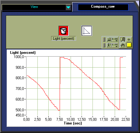
This Robolab test-device uses our new recycled angle-sensor with an 8° resolution. The test-base has a 56:8 ratio, so one turn of the base produces 315 impulses which is largely sufficient.
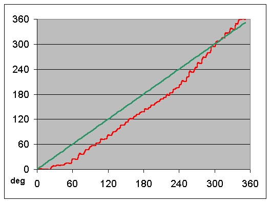
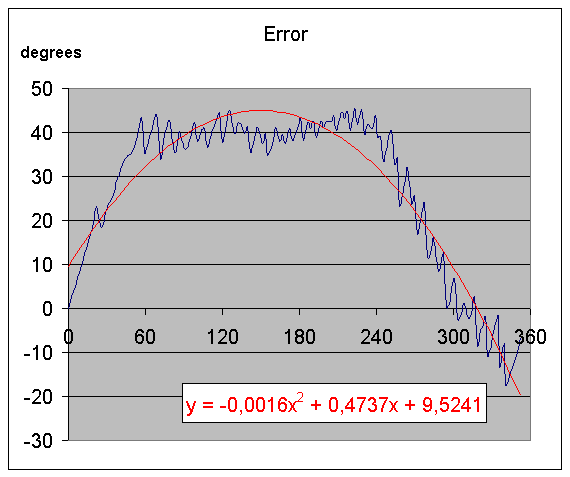
The error-correction should be done in the RCX, for it depends on the individual part-caracteristics and the use-conditions. Have a look at our former projects for better understanding.
6. Download
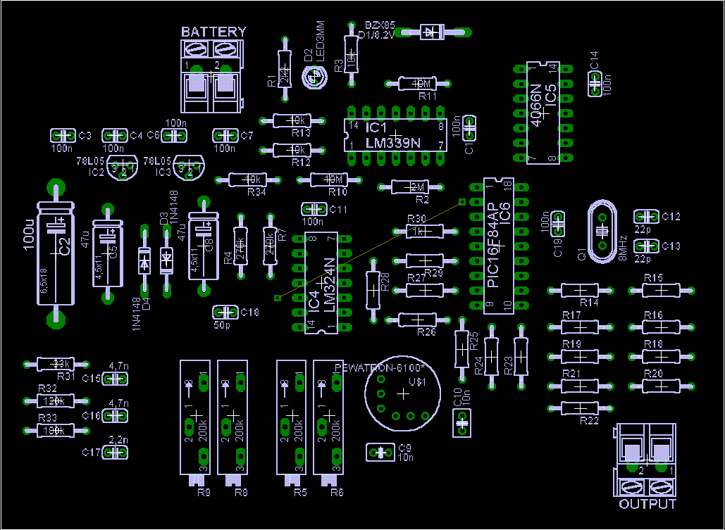
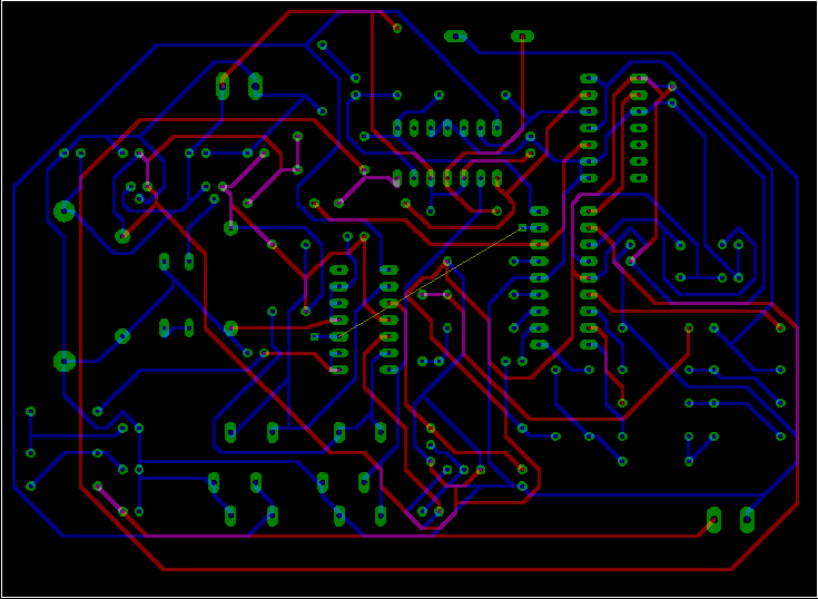
Download all the files. Note that the circuit and the PCBoard have been made with Eagle 4.01.