 Click to see the short video
(160k)
Click to see the short video
(160k)Knight Rider
Click to see the short video
(160k)
With some basic electronics it is possible to multiplex RCX-outputs. What are the possibilities here?
Let's combine the three outputs with the restriction to consider only two positions: FWD-ON (1) and OFF (0). We get 8 different states according to the table:
| C | B | A | State |
| 0 | 0 | 0 | 0 |
| 0 | 0 | 1 | 1 |
| 0 | 1 | 0 | 2 |
| 0 | 1 | 1 | 3 |
| 1 | 0 | 0 | 4 |
| 1 | 0 | 1 | 5 |
| 1 | 1 | 0 | 6 |
| 1 | 1 | 1 | 7 |
It is obvious that the state is equivalent to the decimal value of the binary: b 'CBA' .
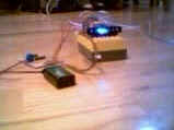
The device we propose here is to control 7 low-current LEDs from the three RCX-outputs.
ATTENTION: CHECK RCX OUTPUT POLARITY BEFORE USE. MALFUNCTION COULD CAUSE SHORT-CIRCUIT IN THE RCX !!!
The digital signal coming from the RCX are decoded in the CMOS 4028 BCD decoder. We add a fast-switching Darlington-net ULN2003 to access the LEDs. Note that value 0 is not multiplexed, so that this value will set all the LEDs OFF. Our animated picture above shows that we chose blue LEDs.
The following ROBOLAB-program will produce a 'Knigh-Rider' LED-show.
Note the dummy zero-container command which is used here for NOP or very short wait. Without this trick, some LEDs will flash, because it seems that the RCX needs more time to shut OFF an output than to put it ON.
The following program allows to control the flashing speed. Connect a 50k potentiometer to RCX Port 1.