5 DOF Robot-arm
(Robolab 2.5)
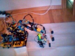
Click to see the video (480kB)
This is a private father-and-son work.
Authors: Claude and Paul-Nicolas Baumann.
Many have tried to conceive a robot-arm with LEGO, so that there exists a huge palette of such devices: ultra-light, -strong, -flexible or -quick. Our idea was to build and exploit a 50cm arm with 5 degrees of freedom (DOF) and a grabber-hand.
The first step was to study some robot-arm theory through books, articles and internet. Then came the building phase followed by the programming and finally the testing.
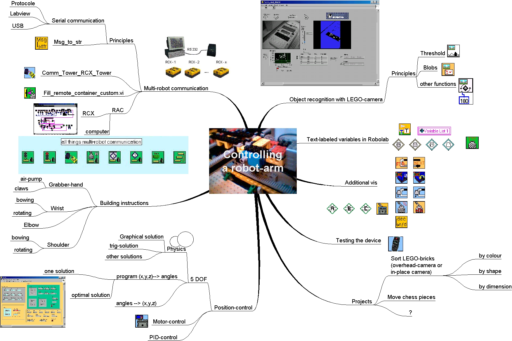
1. Project-overview (click to enlarge)
2. Some theory
Our robot-arm has 5 degrees of freedom (DOF). The grabbing mechanism is not considered as such. The shoulder is bowing and rotating, the elbow and the wrist are only bowing and the hand itself is rotating.
Normally a robot-arm should have 6 DOFs to easily reach every point of the work-space at different incidence-angles. This might be important for example if the hand is used to drill holes, which must be done at a given drill-angle. The project had to be limited to 5 DOFs since there are only 6 actuator-ports available with two RCXs. The sixth port is reserved to control the grabbing-mechanism.
Mathematically it may be shown that you need exactly three independant coordinates to fix a point in space. Let's imagine a cartesian robot-arm which allows three orthogonal translation-movements (TTT) of the hand. The approach differs a lot from the rotational RRR-system above. In this case any point is defined by M(x,y,z):
We note that our robot-arm may reach M through bowing shoulder Q1, elbow Q2 and wrist Q3 and rotating shoulder-base Q0 . Q4 has no positioning influence. It only allows the claws to grab at a better angle. So strictly speaking we have only 4 DOFs. With a closer look we notice that the points M, O1, O2, O3, always are situated in the same plane, when Q0 is rotating.
Thus every point may be fixed by looking at Q0 and the two-dimension coordinates of the M in the rotating plane P .
In most of the cases points are initially defined and entered by cartesian coordinates in what is so called the world coordinate-system. In a first step these world-coordinates have to be transformed to those coordinates in the (O1,O2,O3) plane and a certain unique value of Q0. With the observation that by rotating Q0, the y-coordinates are the same in the world-system and in P, the x-coordinate in P is deduced by Pythagoras.
Defining a point M(xP,y) in a plane with rotations of three segments is obviously possible, but presents some important ambiguity. In fact there are an infinity of possibilties to determine M in terms of (Q1,Q2,Q3). This gives the robot a lot of freedom, but also the necessity of choice, which is the second step to operate.
There are many ways to deduce Q1, Q2 and Q3 from M(xP,y) . The following explanations require some basic geometry-skills.
Geometrical Solution
Given the robot-arm with lengths a, b and c; given the point M(xP,y); given the circle with center O1 and radius a.
We arbitrary fix the radius r2 of the circle with center M respecting the restrictions that at least one intersection of boths circles exist and that r2<=b+c. We choose one of the intersections as point O2. Now the point O3 may be fixed through the intersection(s) of the circle with center M and radius c and the circle with center O2 and radius b.
As we can see, there are 0, 1, 2 or 4 solutions, depending on the choice of r2. If we add the assertion that b is different from c, we never have only 1 solution.
This geometrical approach graphically gives us the three points O1, O2 and O3 as circle intersections. The angles Q1,Q2 and Q3 may be easily deduced.
A computer algorithm requires additional analytical reflections:
here some pseudo-code:
(u-x)2 + (v-y)2 = r22
u2 + v2 = a2
the solution(s) to this system are the possible positions of O2(x2,y2) and O2'(x2',y2')
Optimal solution
As pointed out there exist an infinity of solutions to reach a certain point with 3 articulations. We have to make a choice. Mathematically it makes no sense to speak of choice, if all the possible options have the same weight. In reality however, and specially in this particular case of a robot-arm, there do appear quality-differences in the options.
One of the major problem of a robot-arm is the motion from one point to another. This passage is linked to costs of energy and time. Normally the joints bow at different angular speeds. Due to this, not all the angular positions, which theoretically match the equations above, will have an equivalent weight. Additionally, depending on the design, some points of P may not be reached. Or some (Q1,Q2,Q3)-combinations might be even forbidden: the elbow may not bow over or below a certain limit, the arm may not pass below ground, the wrist may in no case cross the shoulder, a.s.o.
On the other hand, there are some indications which must be respected, for example: let the claws grab only at a certain angle, so hold it them close as possible to that angle ...
Optimizing these kind of conditions is complicated and leads to terribly complex equations, if you try to do so by purely mathematical means. Another way is to let the computer try a certain number of caracteristic cases and isolate the best approximation. That's what we are doing now.
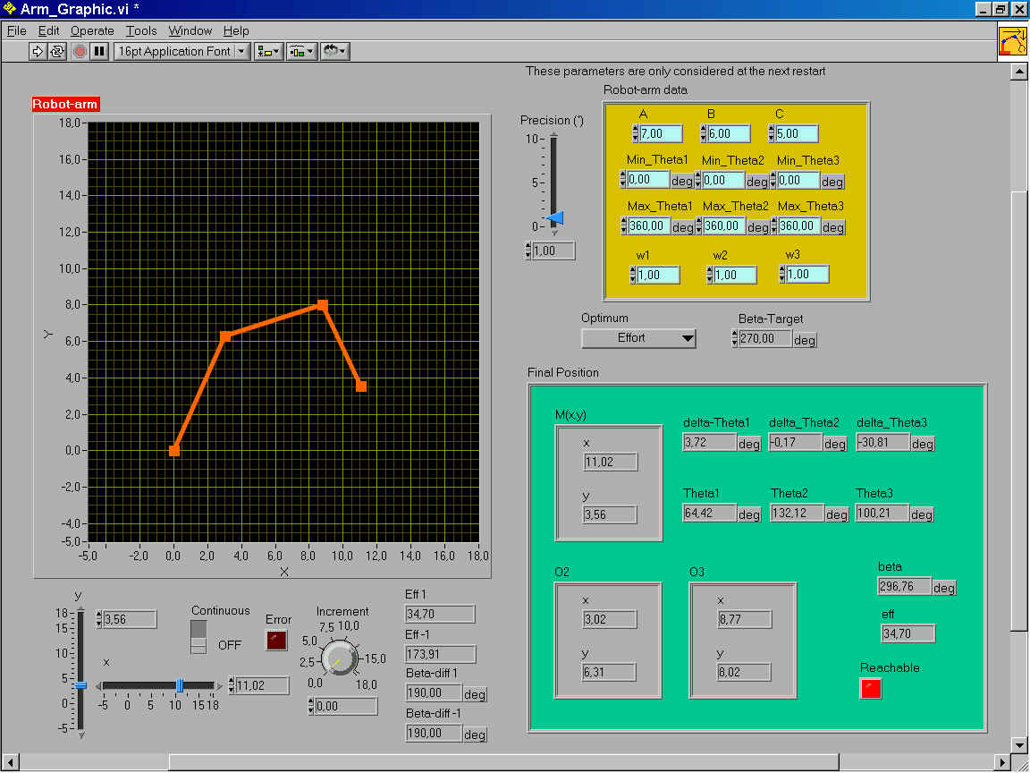
We introduce a special variable called eff, which stands for effort. The angular speed of each articulation represented by the angles Q1,Q2 and Q3 is entered through w1, w2 and w3. This might as well be a relative angular speed (compared to the slowest or the quickest articulation). In the case of real angular speed, eff holds the time, which is necessary to reach the new point from the actual location.
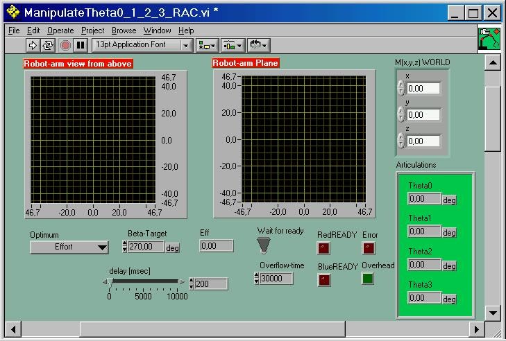
Here a screen-shot of the optimizing process:
Represent the optimal solutions graphically:
3. Multi-RCX communication
Controlling 5 DOF and a grabber-hand requires 6 RCX-input and 6 -output-ports. The complex computing to find optimal positions of the articulations needs a constant communication to the computer. We have to establish a multi-RCX communication.
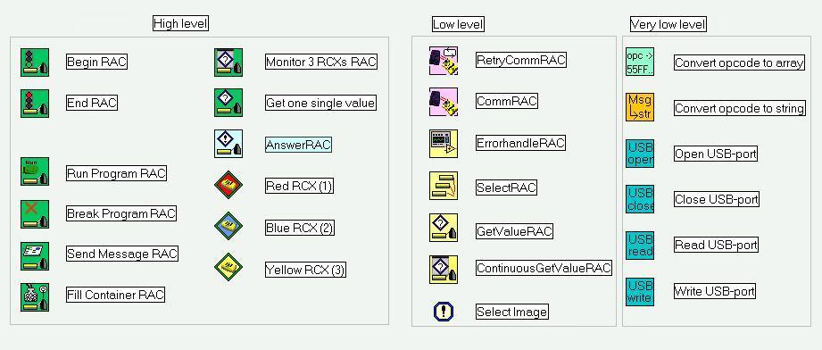
The following icons allow the computer to communicate with several RCXs. Note that none of these sub.vis may be used with original Robolab direct or download functions except for AnswerRAC.vi which must be downloaded to the implied RCXs (see examples below.) However the normal Robolab modifiers may be connected to these Vis. (RAC stands for RCX Allround Communication)
4. Robot-arm direct control
With the following program you may easily control the robot-arm directly.
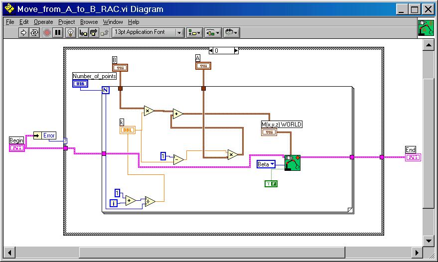
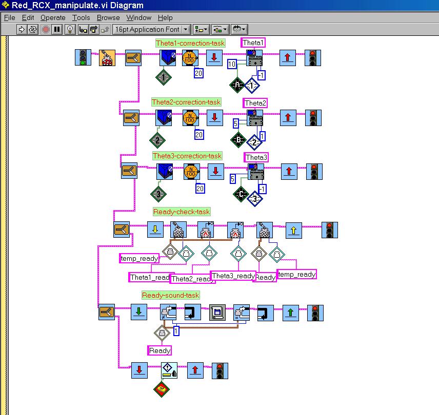
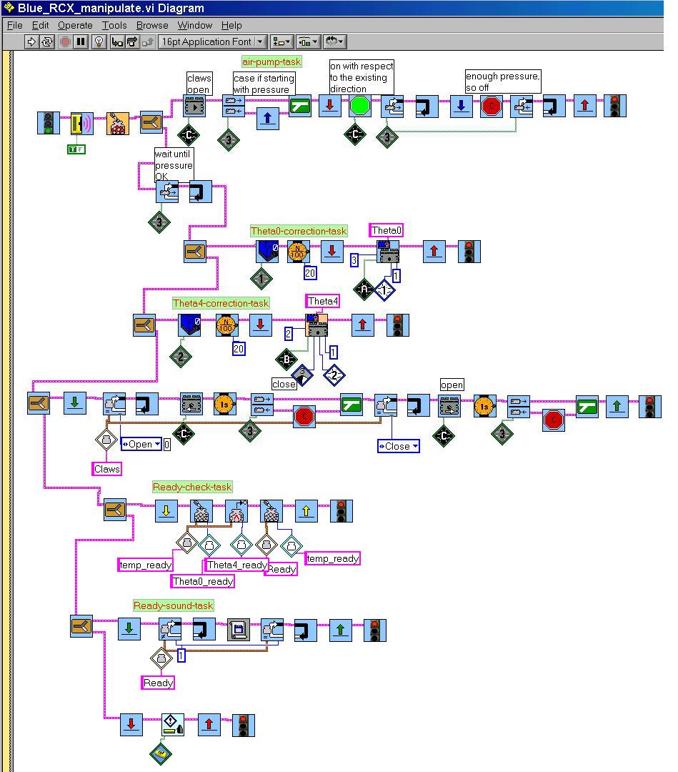
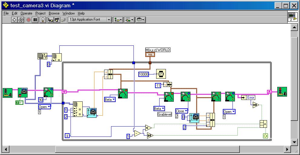
Here an exctract of the program-diagram: it uses the Point_to_point.vi and some multi-RCX communication tools and should be run together with downloaded Red_RCX and Blue_RCX control programs.
5. Camera-equipped robot-arm
The idea is simple: the LEGO-camera is placed at about 80cm from ground to survey a certain area in front of the robot-arm. Several LEGO-pieces are spread over the field. A special software analyses the area for blobs and returns some information such as object coordinates to the robot-arm control program. The arm then moves to every object, grabs it and transports it to a box, where the hand releases the object.
|
|
Some problems have to be solved before
the robot-arm may become active:
|
All this is done through Get_object_positionsRAC.vi.
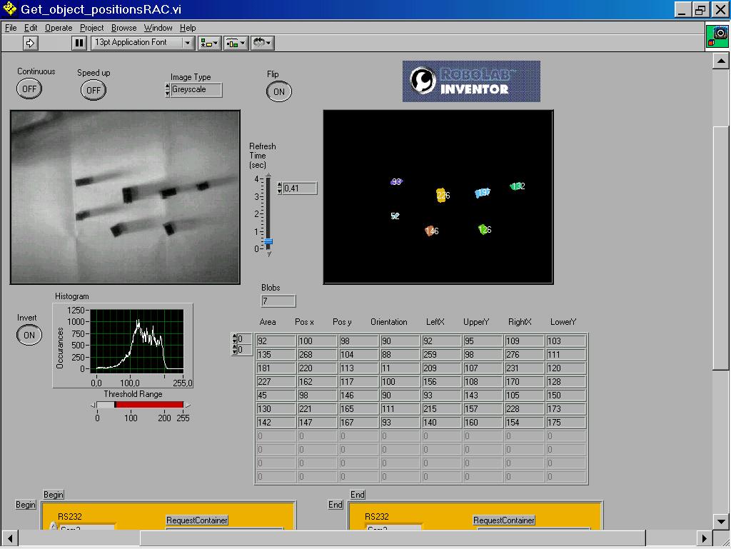
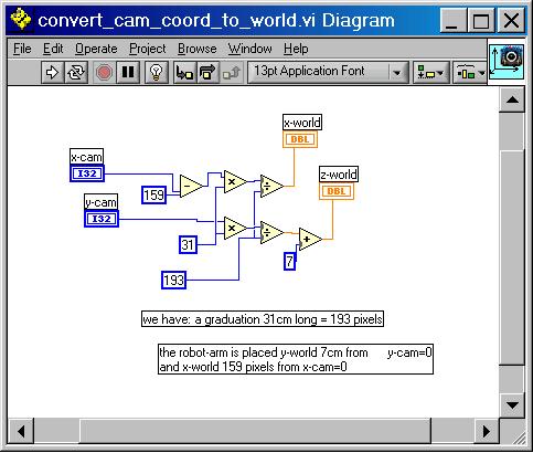
In order to get the right proportionsfrom pixel to cm we simply use a 31cm stick placed parallel to the x-axis and note the difference between RightX and LeftX, which in our case here is 193 pixels. The world-origine's projection on ground-plane has coordinates (x = 159 pixels, y = -7cm). This sounds a bit confusing, but the robot-arm center is situated 7cm from the camera's picture limit and the world z-axis cuts the camera x-axis at coordinate 159 [pixels]. Depending on how you place the camera, you must flip or mirror the image before filtering it.
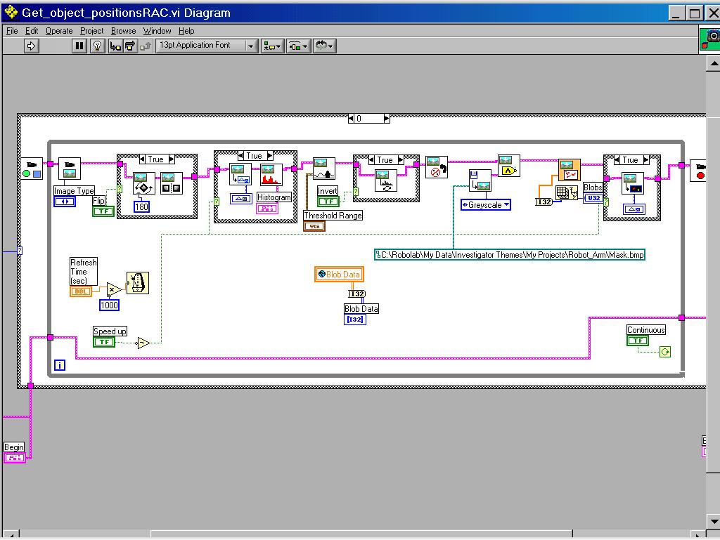
This program controls the robot-arm to localize, grab and store several objects. It uses some important sub.vis to control Red_RCX and Blue_RCX.
The following sub.vi provides the solution to a nasty problem. In fact, while moving from point to point, even if the starting point and the ending point are allowed, it is possible that the robot-arm may move to forbidden intermedium points. This is accuentuated in our case where the articulations move at very different angular velocities. To avoid catastrophes, we sometimes use a linear interpolation-program. If the robot is ordered to move from A to B it will then move to a certain number of intermediary points situated on the segment (A,B). This slows down the movement, but avoids catastrophs. The intermediary points are calculated through the following vector-equations, where the scalar k is evoluating from 0 to 1: